
Introductory Circuit Analysis (13th Edition)
13th Edition
ISBN: 9780133923605
Author: Robert L. Boylestad
Publisher: PEARSON
expand_more
expand_more
format_list_bulleted
Related questions
Question
Find state space representation of the electrical network .
Plot the output
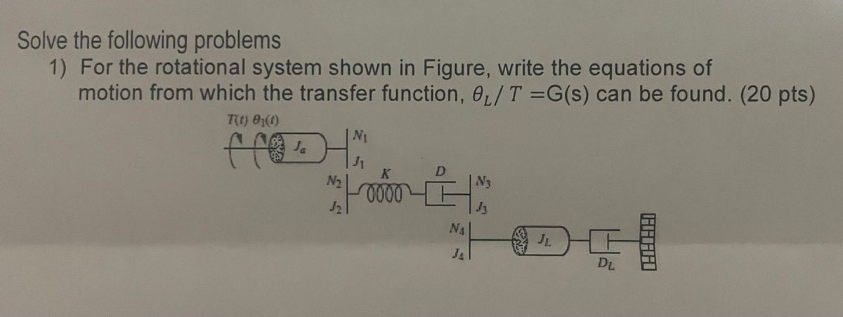

Transcribed Image Text:Solve the following problems
1) For the rotational system shown in Figure, write the equations of
motion from which the transfer function, e₁/T =G(s) can be found. (20 pts)
T(t) 0₁(0)
NI
Ja
K
N₂
№3
0000
√2
NA
JL
JA
DL
Expert Solution
This question has been solved!
Explore an expertly crafted, step-by-step solution for a thorough understanding of key concepts.

Step by stepSolved in 2 steps with 1 images

Knowledge Booster

Similar questions
- Solve question no.06 and show the solution.Note: The answer is given on the bottom right side of the image, just show the solution on how to get it. Also, please explain it step by step.Thanks!!!arrow_forwardPreform AC Steady-State analysis for the circuit calculating the time response function for VRC2, the green probe. R1 50 L1 10mH V1 C2 33u VOFF = 0 VAMPL = 15 FREQ = 200 AC = 0 R2 100arrow_forwardWrite one line of MATLAB code that will generate values of the sinusoid x1 (t) above by using the complex- amplitude representation: x1(t) = Re{Xejwt} Use appropriate constants for X and w.arrow_forward
- Q6. Figure Q6 shows a modulated waveform v(t) in microvolts as a function of time t in nanoseconds. 25 50 75 100 125 150 175 200 225 250 50 40 40 30 30 20 20 10 10 -10 -10 -20 -20 -30 -30 -40 -40 -50 -50 250 25 50 75 100 125 150 175 200 225 time/ns Figure Q6: Modulated waveform (a) Describe the modulation scheme. (b) What are the values of the carrier frequency and the modulation frequency? (c) What is the value of the modulation index? (d) What is the transmission efficiency (ratio of modulated to total power) in this example? (e) Sketch the spectrum of this modulated waveform indicating the relative magnitudes of the various spectral components. (f) The modulating wave in this example is substituted with a square wave of 50% duty cycle and of fundamental frequency 1.0 MHz. Sketch the absolute value of the spec- trum of the modulated waveform indicating the frequencies and relative magnitudes of the sideband components. (g) Demodulation of this type of signal is usually accomplished…arrow_forward6-9) A capacitor, an inductor and a resistor all walk into a bar. No, wait. A capacitor, and inductor, and a resistor are connected in series with a sinusoidal AC emf. At what frequency ω will the maximum voltage drop across the capacitor itself be maximized (VC MAX)MAX? This is a tedious one.arrow_forwardThe second photo is a solution from bartleby expert but they never gave any plot sketches! Can you help me plot the graphs?arrow_forward
- Find the natural frequency for Vc for the following circuit given the following parameters. Solve for the differential equation symbolically so that you can use the same result in the next question. Otherwise you will have to repeat the process with new numbers. Also be wary of the given units. C = 1mF, L = 3mH, R₁ = 42, R₂ = 9 and R3 = 100 12v R₁ t=0 * R₂ R3arrow_forwardLet Zeq be the equivalent impedance of a parallel connection of an inductor with inductance L and a capacitor with capacitance C. At w=1/√√LC, the equivalent impedance is given by O a. Zeq = 0 b. Zeq = 1 O c. Zeq = 00 O d. Zeq = 0.5arrow_forwardA particular circuit built with one resistor and one capacitor in series allows high frequency source voltage sine waves to be transmitted as the output essentially unchanged. Any low frequency source voltage sine waves are “killed”; the output is very small, essentially zero. Design this circuit: draw the circuit and explain whether you measure output over the resistor or capacitor, and why. You do not need to choose values of R and C.arrow_forward
- b) Two circuits connected in series which voltage drop across at each circuit can be expressed in time TTM domain as V1 (t) =5 sin (3147) V and V2 (1) =15 sin (314t - 30°) V. Sketch the waveforms of these voltages to illustrate peak values and phase relationships. UTM 5 UTM UTM TM S UTM UTM TM 5 UTM 8 UTMarrow_forward* ?Find the overall TF of the following system 2s+1 7+44 +3 12+1 * ?obtain the step and sinusoidal response of the system * ?What are the delay time and MP of the system ?is the system stable? prove your answerarrow_forwardPlease help with the attached problem.arrow_forward
arrow_back_ios
SEE MORE QUESTIONS
arrow_forward_ios
Recommended textbooks for you
- Introductory Circuit Analysis (13th Edition)Electrical EngineeringISBN:9780133923605Author:Robert L. BoylestadPublisher:PEARSON
 Delmar's Standard Textbook Of ElectricityElectrical EngineeringISBN:9781337900348Author:Stephen L. HermanPublisher:Cengage Learning
 Programmable Logic ControllersElectrical EngineeringISBN:9780073373843Author:Frank D. PetruzellaPublisher:McGraw-Hill Education
  Fundamentals of Electric CircuitsElectrical EngineeringISBN:9780078028229Author:Charles K Alexander, Matthew SadikuPublisher:McGraw-Hill Education
 Electric Circuits. (11th Edition)Electrical EngineeringISBN:9780134746968Author:James W. Nilsson, Susan RiedelPublisher:PEARSON
 Engineering ElectromagneticsElectrical EngineeringISBN:9780078028151Author:Hayt, William H. (william Hart), Jr, BUCK, John A.Publisher:Mcgraw-hill Education,
Introductory Circuit Analysis (13th Edition)
Electrical Engineering
ISBN:9780133923605
Author:Robert L. Boylestad
Publisher:PEARSON
Delmar's Standard Textbook Of Electricity
Electrical Engineering
ISBN:9781337900348
Author:Stephen L. Herman
Publisher:Cengage Learning
Programmable Logic Controllers
Electrical Engineering
ISBN:9780073373843
Author:Frank D. Petruzella
Publisher:McGraw-Hill Education
Fundamentals of Electric Circuits
Electrical Engineering
ISBN:9780078028229
Author:Charles K Alexander, Matthew Sadiku
Publisher:McGraw-Hill Education
Electric Circuits. (11th Edition)
Electrical Engineering
ISBN:9780134746968
Author:James W. Nilsson, Susan Riedel
Publisher:PEARSON
Engineering Electromagnetics
Electrical Engineering
ISBN:9780078028151
Author:Hayt, William H. (william Hart), Jr, BUCK, John A.
Publisher:Mcgraw-hill Education,