Introductory Circuit Analysis (13th Edition)
13th Edition
ISBN: 9780133923605
Author: Robert L. Boylestad
Publisher: PEARSON
expand_more
expand_more
format_list_bulleted
Question
thumb_up100%

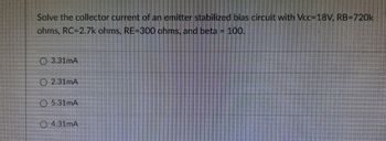
Transcribed Image Text:Solve the collector current of an emitter stabilized bias circuit with Vcc=18V, RB-720k
ohms, RC-2.7k ohms, RE-300 ohms, and beta IF 100.
3.31mA
2.31mA
5.31mA
4.31mA
Expert Solution
This question has been solved!
Explore an expertly crafted, step-by-step solution for a thorough understanding of key concepts.
Step by stepSolved in 2 steps with 2 images

Knowledge Booster
Learn more about
Need a deep-dive on the concept behind this application? Look no further. Learn more about this topic, electrical-engineering and related others by exploring similar questions and additional content below.Similar questions
- Most of the following statements about integrated circuits arecorrect, but one is not. Which statement is NOT true? Select one: a. Transistors are constructed in a small area of an integrated circuit,and are connected to other transistors by wires that are embedded inthe integrated circuit b. Wires that carry signals may be embedded in a substrate without a shortcircuit because a short circuit would require a signal to cross areverse biased junction c. Each transistor on an integrated circuit is manufactured individually,one at a time d. An integrated circuit contains several layersarrow_forwardsolve for the collector saturation current of an emitter stabilized bias circuit with Vcc=18V, RB=720k ohms, RC=2.7k ohms, RE=300 ohms and beta=100. A. 6mA B. 7mA C. 8mA D. 9mAarrow_forwardPrelab: Using the BJT large signal model for the circuit in Figure 1, determine the Vub voltage required to drive a collector current of I, = 0.5 mA. Use RB = 220 kN, Rc = 2.05 kN, RE = 1.05 kN, and Vee = 5V. Assume Is = 50nA and ß = 250. (Hint: Find Vbe using Ic, then use KVL to find Vbb, remember that Ib can be found using the Ic/ ß relationship) RC Voc R3 bb RE Figure 1 NPN BJT under DC Biasarrow_forward
- The emitter current is always… Greater than the base current equal to the collector current Less than the collector current Less than the base currentarrow_forwardSolve the emitter voltage of a voltage-divider bias circuit with Vcc=9V, R1-560k ohms, R2=560k ohms,RC=3.3k ohms, RE-680 ohms, and beta - 100. 0.7V Ⓒ4.7V Ⓒ1.44V ⒸOVarrow_forwardDesign a voltage-divider bias network using a supply of 18 V, a transistor with a beta of 110, and an operating point of Ico = 6 mA and VCEQ = 4 V. Choose VE = 1/8 Vcc. %3D %3D Use BRE = 10R2. %3D 1. How much is the emitter voltage?arrow_forward
- %3D = 13 volts, Rg = 500 KN, Rc = 6 KN and ß = 120. Assume Transistor is Silicon, VBE=0.7v. For the given circuit, Vcc +Vcc Rc RB VCE V BE a Compute for the base current Q-point, IBq (in Amperes): b. Compute for the collector current Q-point, Ico (in Amperes): c. Compute for the collector-to-emitter voltage, VCEQ (in Volts): d. Draw the DC load line with the axes and the points labeled.arrow_forwardGiven the device chara cteristics Vec, RB , and Rc for the Axed- bias con figurahion of Figure 4Cb). of Figure 4 Ca), determine ICCMA) quee Vec @-point -Isa = 4QA A Rs RC VCE IBQ 20V Ca) C6)arrow_forwardDesign the given circuit at Ico = ½ ICSAT and VCEO = 2 Vcc use Vcc = 20 volts, ICSAT = 10 milli ampere, DC beta, B 140 and Rc = 4RE. Vcc %3D %3D Re Rc RE 4. The value of collector resistance (RC) in ohms is 5. The value of emitter current (le) in amperes is 6. The value of the emitter voltage (Ve) in volts is 7. The value of base voltage (Vb) in volts isarrow_forward
- In a MOSFET amplifier, the AC input signal is applied at gate terminal and the amplified output is taken at source terminal. common emitter common gate common source common drainarrow_forward2. Determine the operating point for a fixed-biased transistor with the following values: BDC = 90, Vcc=12 V, RB=22 KO, and Rc=100. Show the circuit too.arrow_forward6.arrow_forward
arrow_back_ios
SEE MORE QUESTIONS
arrow_forward_ios
Recommended textbooks for you
 Introductory Circuit Analysis (13th Edition)Electrical EngineeringISBN:9780133923605Author:Robert L. BoylestadPublisher:PEARSON
 Delmar's Standard Textbook Of ElectricityElectrical EngineeringISBN:9781337900348Author:Stephen L. HermanPublisher:Cengage Learning
 Programmable Logic ControllersElectrical EngineeringISBN:9780073373843Author:Frank D. PetruzellaPublisher:McGraw-Hill Education
 Fundamentals of Electric CircuitsElectrical EngineeringISBN:9780078028229Author:Charles K Alexander, Matthew SadikuPublisher:McGraw-Hill Education
 Electric Circuits. (11th Edition)Electrical EngineeringISBN:9780134746968Author:James W. Nilsson, Susan RiedelPublisher:PEARSON
 Engineering ElectromagneticsElectrical EngineeringISBN:9780078028151Author:Hayt, William H. (william Hart), Jr, BUCK, John A.Publisher:Mcgraw-hill Education,

Introductory Circuit Analysis (13th Edition)
Electrical Engineering
ISBN:9780133923605
Author:Robert L. Boylestad
Publisher:PEARSON

Delmar's Standard Textbook Of Electricity
Electrical Engineering
ISBN:9781337900348
Author:Stephen L. Herman
Publisher:Cengage Learning

Programmable Logic Controllers
Electrical Engineering
ISBN:9780073373843
Author:Frank D. Petruzella
Publisher:McGraw-Hill Education

Fundamentals of Electric Circuits
Electrical Engineering
ISBN:9780078028229
Author:Charles K Alexander, Matthew Sadiku
Publisher:McGraw-Hill Education

Electric Circuits. (11th Edition)
Electrical Engineering
ISBN:9780134746968
Author:James W. Nilsson, Susan Riedel
Publisher:PEARSON

Engineering Electromagnetics
Electrical Engineering
ISBN:9780078028151
Author:Hayt, William H. (william Hart), Jr, BUCK, John A.
Publisher:Mcgraw-hill Education,