Structural Analysis
6th Edition
ISBN: 9781337630931
Author: KASSIMALI, Aslam.
Publisher: Cengage,
expand_more
expand_more
format_list_bulleted
Question
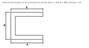
I need help on getting the centroid of this figure please show complete solution. Answer is provided.
Solve for the location of the centroid from the left side.: Answer: 80.74

Transcribed Image Text:Solve for the location of the centroid from the left side. A = 265, B = 400, thickness = 14
A
B
A
SAVE
AI-Generated Solution
info
AI-generated content may present inaccurate or offensive content that does not represent bartleby’s views.
Unlock instant AI solutions
Tap the button
to generate a solution
to generate a solution
Click the button to generate
a solution
a solution
Knowledge Booster
Similar questions
- Determine the location z̅ of the centroid for the tetrahedron. Suggestion: Use a triangular “plate” element parallel to the x–y plane and of thickness dz.arrow_forwardThe shear strain at corner A of the following rectangle with respect to Y-axis is 350 300 All dimensions are in mmarrow_forwardTo lower ends of the three bars in the figure two are the same level before the rigid homogeneous W=176kN block is attached. Each still bar has a length of 1.00 m, an area 500mm² and E=200 GPa. For the bronze bar the length is 1.6m, the area is 900mm² and E= 83 GPa. What is the stress developed in the bronze bar? What is the stress developed into steel bar? What is the elongation of each bar?arrow_forward
- 8. Locate the centroid of the bent wire shown below. The wire is homogeneous and of uniform across section.arrow_forwardA plain scarf joint is used to fabricate a prismatic member to be subjected to pure tension. Calculate the load carrying capacity of the joint if the allowable shear and tensile stresses in the adhesive layer are 26 MPa and 76 MPa, respectively. The normal vector of the inclined section makes an angle of 30 degrees from the centroidal axis of the prismatic member. The cross-sectional area is 300 mm². 30° Parrow_forwardA joint is made by gluing two plywood gussets of thickness t to wood boards. The tensile working stresses are 1200 psi for the plywood and 700 psi for the boards. The working shear stress for the glue is 50 psi. Determine the dimensions b and t so that the joint is as strong as the boards.arrow_forward
- allowa quired wall thickness 2:11 .l 0.31 KB/S 64 Edit 16 A rigid bar AB is hinged at A and is supported by a rod CD at C. The rod is pin connected at D, as shown. Neglect deflections of the bar due to bending. Use E = 200 GPa. 36 mma 2 m OWhat is the displacement of the loaded end B of the bar? ® Determine the tensile stress induced in rod CD by the 80 kN load D If the allowable stress in rod CD is 124 MPa, what weight W can be safely 1.8 m 12m applied? w80 AN 1. A holl ow cir cular steel colum n is s ubjected toa compression load of 380 kN . The column has a length of 2.4 mn.and an outside dia meter of 187.5 mm. E - 200,000 MPa Determine the min. roquired wall thicknesss base on an allo wable com pressi ve stress of 48 MPa. Determine the min. required wall thickness based on 30 MPa. Determine the min. required wall thickness based on the allowable shortening of the colum n to b e 0.5 0 mm- allowable shear stress of C3D P-38 O kN 2.4 m 2. An 8 mm diameter steel rod, 20 m. long…arrow_forwardThe state of stress at a point is shown on the element. Suppose that σ = 14 ksi, oy = 7 ksi and 9 ksi in the directions shown. Txy ox = 01, 02 = σy Өрт, өрг P2 Part A Determine the principal stresses. Express your answers in kilopounds per squared inch to three significant figures separated by a comma. ANSWER: = Txy O x Q Tap image to zoom ksi Part B Specify the orientation of the element. Express your answers in degrees to three significant figures separated by a comma. ANSWER:arrow_forwardNearest Ans - 148 N.marrow_forward
- Use the virtual work method to determine the deformation at joint B of the truss shown. 3 m A -2 m 100 KN B 50 kN -4 m- EA constant E = 70 GPa A = = 1,000 mm² Carrow_forward(c) A thin, triangular plate ABC is uniformly deformed into a shape ABC', as shown by the dashed lines in the figure. Calculate (i) The normal strain along the centreline OC; (ii) The normal strain along the edge AC; and (iii) The shearing strain between the edges AC and BC. b 0-1 b B 90° 10.001barrow_forwardQuestion 2. The square plate ABCD is deformed into the shape shown by the dashed lines. If DC has a normal strain 6x = 0.005, DA has a normal strain e, = 0.004 at D, y = 0.01rad determine the shear strain at point E with respect to the x and y' axes. 600 mm 600 mmarrow_forward
arrow_back_ios
SEE MORE QUESTIONS
arrow_forward_ios
Recommended textbooks for you

 Structural Analysis (10th Edition)Civil EngineeringISBN:9780134610672Author:Russell C. HibbelerPublisher:PEARSON
 Principles of Foundation Engineering (MindTap Cou...Civil EngineeringISBN:9781337705028Author:Braja M. Das, Nagaratnam SivakuganPublisher:Cengage Learning
 Fundamentals of Structural AnalysisCivil EngineeringISBN:9780073398006Author:Kenneth M. Leet Emeritus, Chia-Ming Uang, Joel LanningPublisher:McGraw-Hill Education
 Traffic and Highway EngineeringCivil EngineeringISBN:9781305156241Author:Garber, Nicholas J.Publisher:Cengage Learning


Structural Analysis (10th Edition)
Civil Engineering
ISBN:9780134610672
Author:Russell C. Hibbeler
Publisher:PEARSON

Principles of Foundation Engineering (MindTap Cou...
Civil Engineering
ISBN:9781337705028
Author:Braja M. Das, Nagaratnam Sivakugan
Publisher:Cengage Learning

Fundamentals of Structural Analysis
Civil Engineering
ISBN:9780073398006
Author:Kenneth M. Leet Emeritus, Chia-Ming Uang, Joel Lanning
Publisher:McGraw-Hill Education


Traffic and Highway Engineering
Civil Engineering
ISBN:9781305156241
Author:Garber, Nicholas J.
Publisher:Cengage Learning