Introductory Circuit Analysis (13th Edition)
13th Edition
ISBN: 9780133923605
Author: Robert L. Boylestad
Publisher: PEARSON
expand_more
expand_more
format_list_bulleted
Concept explainers
Question
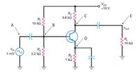
A small signal amplifier as shown in the picture. If the input signal is sinusoidal 1 mVpp and β = 100, find:
the load line and the Q point of the amplifier

Transcribed Image Text:Vcc
+10 V
Rc
3.6 k2
C
E
R,
10 ΚΩ
A
В
Vout
D
RL
10 k2
Vin
R2
1 mV
2.2 k2
RE
1 k2
Expert Solution
This question has been solved!
Explore an expertly crafted, step-by-step solution for a thorough understanding of key concepts.
Step by stepSolved in 2 steps with 2 images

Knowledge Booster
Learn more about
Need a deep-dive on the concept behind this application? Look no further. Learn more about this topic, electrical-engineering and related others by exploring similar questions and additional content below.Similar questions
- You are tasked with designing a linear amplifier using an NPN BJT for the circuit shown below. This means the transistor iv curves apply here. The voltages given are Vcc = 14 V and Vs = 1.0 V. The datasheet for the transistor says VBE (ON) = 0.7 V,VCE (SAT) = 0.2 V, and ß = 400. The design should have ic = 12 mA and VCE = 8 V. Find the resistances Rb and Rc that give the required ic and VCE. Vs H Rb M d VBE Rc VCE Vccarrow_forwardA common emitter amplifier has a 15V power supply. If we design for a 6.5V swing (peak voltage) at the output voltage what will the DC voltage drop be across RE? Group of answer choices 2V 10V 6.5 5Varrow_forward4) Consider the amplifier shown below with its corresponding small signal model. Using the provided small signal model, perform small signal analysis to determine expressions the you would need to determine Av(s). Do NOT solve for Av(s), just provide the expressions that you would need to determine Av(s). Show your work! Do NOT make any approximations. Vin Cf Vcc WWW R Vo CL Vin W R1 Cf + Vberπ ww R gm Vbe W ro Vo CLarrow_forward
- An RF amplifier is composed of a cascade of two amplifier devices. The first has a power gain of 190W/W. The second has a power gain of 100W/W. What is the overall power gain of the cascade in dB (to two decimal places)?arrow_forwardFigure 2 shows a typical BJT amplifier, with its parasitic capacitances displayed. The current gain of the transistor is B=150 and the voltage gain of the amplifier is Am =-125. The small signal resistances of the transistor are re =16 ohm and r0 = infinity, respectively. The values of resistors and capacitors in the figure are: R1 =80 kohm, R2 =20 Kohm, Rc = 2 Kohm, RE = 2 Kohm, Rs =50 W, RI=5 kohm, Cs=2 uF, Cc=2 uF, Ce =10 uF, Cbc =4 pF, Cbe = 10 pF, Cce =1 pF, Cwi = 4 pF, CWO = 9 pF, and Vcc = 20 V. a) Sketch a simplified circuit diagram of Figure 2 for high frequency analysis. b) Using the concept of "Miller effect capacitance", calculate the input and Output Miller effect capacitances of Figure 2, respectively. C) Determine the upper cut-off frequency of Figure 2 that is imposed by its input network only. d) Explain briefly the possible ways to increase the upper cut-off frequencv of this amplifier.arrow_forwardIn an NPN transistor used as an amplifier, which components or connections control the current flow between the others? Pick those that apply. Either N-doped regions. The base, symbolized by B controls the current between the emitter, symbolized by E, and the collector, symbolized by C. The emitter, symbolized by E controls the current between the base, symbolized by B, and the collector, symbolized by C. The P-doped depletion region.arrow_forward
arrow_back_ios
arrow_forward_ios
Recommended textbooks for you
 Introductory Circuit Analysis (13th Edition)Electrical EngineeringISBN:9780133923605Author:Robert L. BoylestadPublisher:PEARSON
 Delmar's Standard Textbook Of ElectricityElectrical EngineeringISBN:9781337900348Author:Stephen L. HermanPublisher:Cengage Learning
 Programmable Logic ControllersElectrical EngineeringISBN:9780073373843Author:Frank D. PetruzellaPublisher:McGraw-Hill Education
 Fundamentals of Electric CircuitsElectrical EngineeringISBN:9780078028229Author:Charles K Alexander, Matthew SadikuPublisher:McGraw-Hill Education
 Electric Circuits. (11th Edition)Electrical EngineeringISBN:9780134746968Author:James W. Nilsson, Susan RiedelPublisher:PEARSON
 Engineering ElectromagneticsElectrical EngineeringISBN:9780078028151Author:Hayt, William H. (william Hart), Jr, BUCK, John A.Publisher:Mcgraw-hill Education,

Introductory Circuit Analysis (13th Edition)
Electrical Engineering
ISBN:9780133923605
Author:Robert L. Boylestad
Publisher:PEARSON

Delmar's Standard Textbook Of Electricity
Electrical Engineering
ISBN:9781337900348
Author:Stephen L. Herman
Publisher:Cengage Learning

Programmable Logic Controllers
Electrical Engineering
ISBN:9780073373843
Author:Frank D. Petruzella
Publisher:McGraw-Hill Education

Fundamentals of Electric Circuits
Electrical Engineering
ISBN:9780078028229
Author:Charles K Alexander, Matthew Sadiku
Publisher:McGraw-Hill Education

Electric Circuits. (11th Edition)
Electrical Engineering
ISBN:9780134746968
Author:James W. Nilsson, Susan Riedel
Publisher:PEARSON

Engineering Electromagnetics
Electrical Engineering
ISBN:9780078028151
Author:Hayt, William H. (william Hart), Jr, BUCK, John A.
Publisher:Mcgraw-hill Education,