Introductory Circuit Analysis (13th Edition)
13th Edition
ISBN: 9780133923605
Author: Robert L. Boylestad
Publisher: PEARSON
expand_more
expand_more
format_list_bulleted
Question

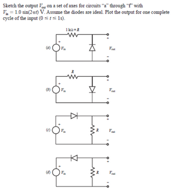
Transcribed Image Text:Sketch the output on a set of axes for circuits "a" through "f" with
V=1.0 sin(2πt) V. Assume the diodes are ideal. Plot the output for one complete
cycle of the input (0 ≤t≤1s).
(a)
1k-R
www
Vout
(b)
Expert Solution
This question has been solved!
Explore an expertly crafted, step-by-step solution for a thorough understanding of key concepts.
Step by stepSolved in 2 steps with 1 images

Knowledge Booster
Similar questions
- A clipper circuit based on diodes are simple way to modify waveform in mechatronics. Assume that the two diodes shown in the circuit below are ideal diodes. If the input voltage in the circuit is a 1 kHz sinusoid with peak amplitude of 8V, sketch the Va.. (t) 10 kO 8V 10 kO Vin Vin(t) D2 Vout(t) RL Ims D1 6V -8V 4V Page | 1arrow_forwardcan you solve this question handwritten solution step by step how did we obtain the v0 graph? my question is not a part of a graded assignmentarrow_forwardDetermine which diodes are forward-biased and which are reverse-biased in the configurations.. Assuming a 0.7-V drop across each forward-biased diode, determine the output voltage.arrow_forward
- In the circuit below, Vi = 6sin (wt) and diodes are considered ideal diodes. Describe the working principle in detail by drawing the output signal. 10KO D2 10KO V. VaC D1 4V 2Varrow_forwardIn the circuit of the following figure, the input voltage Vs is 15 volts rms with a frequency of 60 Hz, R equals 150 Ohms and C equals 100,000 Pico Farads. The diodes are Germanium (Vd = 0.2 volts) and the Zener diode is 12 volts. a) The magnitude of the ripple voltage at Cb) The Magnitude of the Peak Inverse Voltage (PIV) for D1 and D2.arrow_forwardIf one of the diodes in the figure below is open, the average voltage across the load is:(a) increases (b) decreases (c) does not changearrow_forward
- Electronics 1 / Diodesarrow_forwardDraw the output waveform of the following Clamper’s circuits while the input is given below and biasing voltage (V=5v) is 5 v. Practical silicon diode is to be considered for analysis to draw output waveform.arrow_forwardHow do you identify the anode of an unmarked diode? When the forward current of a diode increases, its forward resistance The current flowing in a reverse-biased diode circuit is extremely while the resistance of the diode is extremely The Vz of a zener diode will fairly constant even if the power supply voltage The series resistor Rs is used with the zener diode to the zener current Iz to a level.arrow_forward
- Diode circuitsFor each circuit below, use the diode approximation with forward dropVF= 0.7 V to find the output voltage. No current flows to the output.arrow_forwardDetermine which diodes are forward-biased and which are reverse-biased in the configurations shown in Figure 4. Assuming a 0.7-V drop across each forward-biased diode, determine the output voltage. O+5 V -10 V R DI +s vOK D, -SVOKH D3 +s vOK D4 -5 voK DI -5VOK Dz OVout OVout +5 voK Figure 4.arrow_forwardGiven the following circuit with VDD= 9.2 V, R=2.3 k2, then the current Iis: Use the CVD model for the diode, with VD = 0.65 V. I VDD a. 0.004000 A O b. 3.717391 A OC. 0 A d. 4.000000 A e. 0.003717 A R + VD -arrow_forward
arrow_back_ios
SEE MORE QUESTIONS
arrow_forward_ios
Recommended textbooks for you
 Introductory Circuit Analysis (13th Edition)Electrical EngineeringISBN:9780133923605Author:Robert L. BoylestadPublisher:PEARSON
 Delmar's Standard Textbook Of ElectricityElectrical EngineeringISBN:9781337900348Author:Stephen L. HermanPublisher:Cengage Learning
 Programmable Logic ControllersElectrical EngineeringISBN:9780073373843Author:Frank D. PetruzellaPublisher:McGraw-Hill Education
 Fundamentals of Electric CircuitsElectrical EngineeringISBN:9780078028229Author:Charles K Alexander, Matthew SadikuPublisher:McGraw-Hill Education
 Electric Circuits. (11th Edition)Electrical EngineeringISBN:9780134746968Author:James W. Nilsson, Susan RiedelPublisher:PEARSON
 Engineering ElectromagneticsElectrical EngineeringISBN:9780078028151Author:Hayt, William H. (william Hart), Jr, BUCK, John A.Publisher:Mcgraw-hill Education,

Introductory Circuit Analysis (13th Edition)
Electrical Engineering
ISBN:9780133923605
Author:Robert L. Boylestad
Publisher:PEARSON

Delmar's Standard Textbook Of Electricity
Electrical Engineering
ISBN:9781337900348
Author:Stephen L. Herman
Publisher:Cengage Learning

Programmable Logic Controllers
Electrical Engineering
ISBN:9780073373843
Author:Frank D. Petruzella
Publisher:McGraw-Hill Education

Fundamentals of Electric Circuits
Electrical Engineering
ISBN:9780078028229
Author:Charles K Alexander, Matthew Sadiku
Publisher:McGraw-Hill Education

Electric Circuits. (11th Edition)
Electrical Engineering
ISBN:9780134746968
Author:James W. Nilsson, Susan Riedel
Publisher:PEARSON

Engineering Electromagnetics
Electrical Engineering
ISBN:9780078028151
Author:Hayt, William H. (william Hart), Jr, BUCK, John A.
Publisher:Mcgraw-hill Education,