Structural Analysis
6th Edition
ISBN: 9781337630931
Author: KASSIMALI, Aslam.
Publisher: Cengage,
expand_more
expand_more
format_list_bulleted
Concept explainers
Question

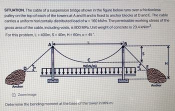
Transcribed Image Text:SITUATION. The cable of a suspension bridge shown in the figure below runs over a frictionless
pulley on the top of each of the towers at A and B and is fixed to anchor blocks at D and E. The cable
carries a uniform horizontally distributed load of w = 160 kN/m. The permissible working stress of the
gross area of the cable, including voids, is 800 MPa. Unit weight of concrete is 23.4 kN/m³.
For this problem, L= 400m, S = 40m, H = 60m, a = 45°.
L
HI
W(kN/m)
E
Anchor
Zoom image
Determine the bending moment at the base of the tower in MN-m:
Anchor
Expert Solution
This question has been solved!
Explore an expertly crafted, step-by-step solution for a thorough understanding of key concepts.
This is a popular solution
Trending nowThis is a popular solution!
Step by stepSolved in 3 steps with 3 images

Knowledge Booster
Learn more about
Need a deep-dive on the concept behind this application? Look no further. Learn more about this topic, civil-engineering and related others by exploring similar questions and additional content below.Similar questions
- 6. The wood pole shown in the Figure 4 is supported by two cables of 4 inch diameter. The turnbuckles in the cable are tightened until the stress in the cables reaches 60,000 psi. if the working compressive stress for wood is 200 psi, determine the smallest permissible diameter of the pole. 60° FIGURE 4 60°arrow_forwardSITUATION. The cable of a suspension bridge shown in the figure below runs over a frictionless pulley on the top of each of the towers at A and B and is fixed to anchor blocks at D and E. The cable carries a uniform horizontally distributed load of w = 160 kN/m. The permissible working stress of the gross area of the cable, including voids, is 800 MPa. Unit weight of concrete is 23.4 kN/m³. For this problem, L= 400m, S = 40m, H = 60m, a = 45°. L H W(kN/m) F Anchor Zoom image Determine the required volume of the concrete anchor blocks in m³. 2600 2800 3000 2500 Anchorarrow_forward1) A box beam has the following dimensions: h = 500 mm, b = 180 mm, and t = 22 mm. If the yield stress is 270 MPa, what is the yield moment? (Express your answer in kN-m, up to 1 decimal place) 2) A box beam has the following dimensions: h = 500 mm, b = 180 mm, and t = 22 mm. If the yield stress is 270 MPa, what is the shape factor? (Express your answer up to 1 decimal place)arrow_forward
- Kindly quick as possiblearrow_forwardProblem The composite bar system in Figure 4.8 consists of a steel bar and a bronze bar that are both securely attached to a rigid block and rigid supports. The system is loaded with a total load P at the rigid block. If the total applied load P=42000 lb, determine the stresses in the two bars. 6′ S TE FIGURE 1.48 Composite bar system for Problem 12. Steel bar } Rigid block -} Bronze bar E₂ = 30 x 10º psi A₂ = 1 in² E-15 x 10 psi Ag-4 in²arrow_forward
arrow_back_ios
arrow_forward_ios
Recommended textbooks for you

 Structural Analysis (10th Edition)Civil EngineeringISBN:9780134610672Author:Russell C. HibbelerPublisher:PEARSON
 Principles of Foundation Engineering (MindTap Cou...Civil EngineeringISBN:9781337705028Author:Braja M. Das, Nagaratnam SivakuganPublisher:Cengage Learning
 Fundamentals of Structural AnalysisCivil EngineeringISBN:9780073398006Author:Kenneth M. Leet Emeritus, Chia-Ming Uang, Joel LanningPublisher:McGraw-Hill Education
 Traffic and Highway EngineeringCivil EngineeringISBN:9781305156241Author:Garber, Nicholas J.Publisher:Cengage Learning


Structural Analysis (10th Edition)
Civil Engineering
ISBN:9780134610672
Author:Russell C. Hibbeler
Publisher:PEARSON

Principles of Foundation Engineering (MindTap Cou...
Civil Engineering
ISBN:9781337705028
Author:Braja M. Das, Nagaratnam Sivakugan
Publisher:Cengage Learning

Fundamentals of Structural Analysis
Civil Engineering
ISBN:9780073398006
Author:Kenneth M. Leet Emeritus, Chia-Ming Uang, Joel Lanning
Publisher:McGraw-Hill Education


Traffic and Highway Engineering
Civil Engineering
ISBN:9781305156241
Author:Garber, Nicholas J.
Publisher:Cengage Learning