Structural Analysis
6th Edition
ISBN: 9781337630931
Author: KASSIMALI, Aslam.
Publisher: Cengage,
expand_more
expand_more
format_list_bulleted
Question

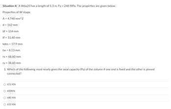
Transcribed Image Text:Situation 4: A W6x25 has a length of 5.3 m. Fy = 248 MPa. The properties are given below.
Properties of W shape
A 4,740 mm^2
d = 162 mm
bf 154 mm
tf = 11.60 mm
kdes 17.9 mm
tw = 8.13 mm
rx = 68.60 mm
ry = 38.60 mm
1. Which of the following most nearly gives the axial capacity (Pu) of the column if one end is fixed and the other is pinned
connected?
O 651 KN
O 600KN.
O 680 KN
O 633 KN
Expert Solution
This question has been solved!
Explore an expertly crafted, step-by-step solution for a thorough understanding of key concepts.
This is a popular solution
Trending nowThis is a popular solution!
Step by stepSolved in 2 steps

Knowledge Booster
Learn more about
Need a deep-dive on the concept behind this application? Look no further. Learn more about this topic, civil-engineering and related others by exploring similar questions and additional content below.Similar questions
- The W10 x 45 is made of A-36 steel and is used as a column that has a length of 15 ft. (Figure 1) Figure I P 15 ft 1 of 1 Part A If its ends are assumed pin supported, and it is subjected to an axial load of 90 kip, determine the factor of safety with respect to buckling. Express your answer using three significant figures. IT ΑΣΦ ↓↑ vec F.S= Submit Request Answer < Return to Assignment Provide Feedback ?arrow_forwardNumber 9arrow_forwardTwo torque as shown are applied on a compound shaft of aluminum segment and a steel. Determine the maximum permissible value of T subjected to the following conditions: T, s 90MPA, T. S 65MPA and the angle of rotation of the free end limited to 11°. Use GS 84 GPa and Ga = 27 GPa. %3D %3D 75 mm Aluminum Steel 50 mm 2 m 1.5 marrow_forward
- xsl: A beam ABCDE is 5 m in length and loaded as shown in Figure Q3. Draw the S.F. and B.M./diagrams for the beam, indicating all major values. A 2 m 2000 Nm 2m 200 N/m M 2 m D 2 m 100 N/m Pays F 2 marrow_forwardThe 22-mm-diameter A-36 steel rod is subjected to the axial forces shown. Take E = 200 GPa. (Figure 1) Figure 1 A of 1 600 mm B 400 mm 50 kN 50 kN C 40 kN MILA Determine the displacement of end C with respect to the fixed support at A. Express your answer to three significant figures and include the appropriate units. 1 dc = Submit μÅ Value Units My Answers Give Up ?arrow_forwardA frame has dimensions and loadings as shown in the figure and parameter table. Determine the horizontal and vertical support reactions that the pins exert on the frame at A and C. Take postive directions to be to the right, and up. 080 BY NO SA 2021 Cathy Zupke parameter Force Ax Force Ay= Force Co = Force Cy= = W L₁ L2 A value 1 3 4.5 -L₂- units kN/m m m KN KN KN KN C B Warrow_forward
arrow_back_ios
arrow_forward_ios
Recommended textbooks for you

 Structural Analysis (10th Edition)Civil EngineeringISBN:9780134610672Author:Russell C. HibbelerPublisher:PEARSON
 Principles of Foundation Engineering (MindTap Cou...Civil EngineeringISBN:9781337705028Author:Braja M. Das, Nagaratnam SivakuganPublisher:Cengage Learning
 Fundamentals of Structural AnalysisCivil EngineeringISBN:9780073398006Author:Kenneth M. Leet Emeritus, Chia-Ming Uang, Joel LanningPublisher:McGraw-Hill Education
 Traffic and Highway EngineeringCivil EngineeringISBN:9781305156241Author:Garber, Nicholas J.Publisher:Cengage Learning


Structural Analysis (10th Edition)
Civil Engineering
ISBN:9780134610672
Author:Russell C. Hibbeler
Publisher:PEARSON

Principles of Foundation Engineering (MindTap Cou...
Civil Engineering
ISBN:9781337705028
Author:Braja M. Das, Nagaratnam Sivakugan
Publisher:Cengage Learning

Fundamentals of Structural Analysis
Civil Engineering
ISBN:9780073398006
Author:Kenneth M. Leet Emeritus, Chia-Ming Uang, Joel Lanning
Publisher:McGraw-Hill Education


Traffic and Highway Engineering
Civil Engineering
ISBN:9781305156241
Author:Garber, Nicholas J.
Publisher:Cengage Learning