Structural Analysis
6th Edition
ISBN: 9781337630931
Author: KASSIMALI, Aslam.
Publisher: Cengage,
expand_more
expand_more
format_list_bulleted
Question

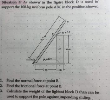
Transcribed Image Text:Situation 3: As shown in the figure block D is used to
support the 100-kg uniform pole. ABC in the position shown..
1.
2.
3.
7.5 m-
A=0.2
-3 m-
-0.2.
D
11
C
4 m
.
Find the normal force at point B.
Find the frictional force at point B.
Calculate the weight of the lightest block D than can be.
used to support the pole against impending sliding..
Expert Solution
This question has been solved!
Explore an expertly crafted, step-by-step solution for a thorough understanding of key concepts.
Step by stepSolved in 2 steps with 2 images

Knowledge Booster
Learn more about
Need a deep-dive on the concept behind this application? Look no further. Learn more about this topic, civil-engineering and related others by exploring similar questions and additional content below.Similar questions
- 1. The uniform 2200-lb bar BC is supported by a pin at C and the aluminum wire AB. The cross-sectional area of the wire is 0.165 in2. Assuming bar BC to be rigid, find the vertical displacement of B due to the weight of the bar. Use E = 10.6 x 10⁶ psi for aluminum. A 6 ft 10 ftarrow_forwardPls solve A and Barrow_forward1.1arrow_forward
- Apply the asymmetric bending theory to the cantilever beam shown below to determine:I. Main moments and inertias.II. The angle of the neutral axis respect the horizontal.III. If ???? = (table) ???, work out the maximum F force that can be applied.3L = (7.5) mb = (57) cmh = (47) cmθ = (56) ° mpa 30arrow_forwardg) the value of the constant of integration C4. Enter your answer in kNm3 to 3 decimal places.arrow_forward1. Figure Q1 shows a simplified diagram of a Ram Air Turbine (RAT), where the force on the rotor is represented by the 2 kN load shown. a. Produce shear and moment diagrams for the supporting frame ABC. b. Calculate the horizontal deflection of the point of loading. Assume that frame ABC has bending stiffness El = 2.7×10⁵ Nm². 0.9 m A 0.6 m C B 2 KNarrow_forward
- F2 =300 N F1 F=700 N 60 м, -1500 Nm 2 m 3m For the above diagram, given that F, = 450 N, 8 = 30 degrees and d = 4 m, calculate the following (neglect the depth of the beam). Note that there is a pin support at A and a roller support at B. The magnitude of the resultant of the applied forces, FR. Please provide the answer in kilo Newtons and report to three significant figures. Please include the unit ("kN") within your answer (e.g. if the calculated answer was 55.562 Newtons please input 55.6 kN). Answer: The angle between the resultant force, FRand the negative x axis (measured anti clockwise from the negative x axis). Please provide the answer in degrees and report to three significant figures. Please include the unit ("deg") within your answer (e.g. if the calculated answer was 55.562 degrees please input: 55.6 deg). Answer: Locate the resultant force, FR, so that it is equivalent to the system of applied forces. Calculate the offset distance of the resultant force, FR, measured…arrow_forwardPROBLEM 5: In the figure shown below, u = 0.3 for all contact surface. ma = 150 kg, mb = 200 kg P B 40 a. If e = 0, find P for motion to impend to the right. b. If e = 0, find P to just prevent the motion.arrow_forwardQuestion 5 The plastic sheet, 1/2 in. thick, is bonded to the pin-jointed steel frame. Determine the magnitude of the force P that would result in a 0.18-in. horizontal displacement of bar AB. Use G = 70 x 10 psi for the plastic, and neglect the deformation of the steel frame. A 3 ft B 2 ft Plastic sheet 2.arrow_forward
- The 679-N force is applied to the 114-kg block, which is stationary before the force is applied. Determine the magnitude and direction of the friction force F exerted by the horizontal surface on the block. The force is positive if to the right, negative if to the left. H₂ = 0.77 = 0.60 Answer: F= i 26° N P = 679 Narrow_forwardA rigid bar AB is hinged at A and is supported by a rod CD at C. The rod is pin connected at D, as shown. What is the displacement of the loaded end B of the bar in mm? Neglect deflections of the bar due to bending. Use E=200 GPa. = 2.6 m a b = 2.1 m c = 1.2 m w = 62 kN с 36 mme Barrow_forwardQuestion 3 T/2 A 1200 Nm A homogeneous steel shaft (G=83GPA) loaded as shown in the above Figure. Assuming T = 300 N-m, determine the torsional force in N-m in Member AB. Note: Include sign (+/-), assuming the direction of Torsion (T) at D is positive Given: AB: Length = 1.75m, Diameter = 75mm BC: Length = 1.50m, Diameter = 60mm AB: Length = 1.00m, Diameter = 40mmarrow_forward
arrow_back_ios
SEE MORE QUESTIONS
arrow_forward_ios
Recommended textbooks for you

 Structural Analysis (10th Edition)Civil EngineeringISBN:9780134610672Author:Russell C. HibbelerPublisher:PEARSON
 Principles of Foundation Engineering (MindTap Cou...Civil EngineeringISBN:9781337705028Author:Braja M. Das, Nagaratnam SivakuganPublisher:Cengage Learning
 Fundamentals of Structural AnalysisCivil EngineeringISBN:9780073398006Author:Kenneth M. Leet Emeritus, Chia-Ming Uang, Joel LanningPublisher:McGraw-Hill Education
 Traffic and Highway EngineeringCivil EngineeringISBN:9781305156241Author:Garber, Nicholas J.Publisher:Cengage Learning


Structural Analysis (10th Edition)
Civil Engineering
ISBN:9780134610672
Author:Russell C. Hibbeler
Publisher:PEARSON

Principles of Foundation Engineering (MindTap Cou...
Civil Engineering
ISBN:9781337705028
Author:Braja M. Das, Nagaratnam Sivakugan
Publisher:Cengage Learning

Fundamentals of Structural Analysis
Civil Engineering
ISBN:9780073398006
Author:Kenneth M. Leet Emeritus, Chia-Ming Uang, Joel Lanning
Publisher:McGraw-Hill Education


Traffic and Highway Engineering
Civil Engineering
ISBN:9781305156241
Author:Garber, Nicholas J.
Publisher:Cengage Learning