
Structural Analysis
6th Edition
ISBN: 9781337630931
Author: KASSIMALI, Aslam.
Publisher: Cengage,
expand_more
expand_more
format_list_bulleted
Related questions
Question
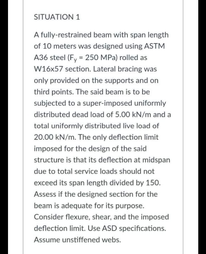

Transcribed Image Text:SITUATION 1
A fully-restrained beam with span length
of 10 meters was designed using ASTM
A36 steel (Fy = 250 MPa) rolled as
W16x57 section. Lateral bracing was
only provided on the supports and on
third points. The said beam is to be
subjected to a super-imposed uniformly
distributed dead load of 5.00 kN/m and a
total uniformly distributed live load of
20.00 kN/m. The only deflection limit
imposed for the design of the said
structure is that its deflection at midspan
due to total service loads should not
exceed its span length divided by 150.
Assess if the designed section for the
beam is adequate for its purpose.
Consider flexure, shear, and the imposed
deflection limit. Use ASD specifications.
Assume unstiffened webs.
Expert Solution
This question has been solved!
Explore an expertly crafted, step-by-step solution for a thorough understanding of key concepts.

Step by stepSolved in 4 steps with 25 images

Knowledge Booster


Learn more about
Need a deep-dive on the concept behind this application? Look no further. Learn more about this topic, civil-engineering and related others by exploring similar questions and additional content below.Similar questions
- A 35-feet simply-supported floor beam, made of ASTM A572 Gr. 50 (Fy = 50 ksi) W18x50 hot-rolled section bent about its major axis, is to carry a superimposed uniform dead load of 0.45 kip/ft and uniform live load of 0.75 kip/ft throughout its entire span. The beam is braced against lateral deflection at its supports and at its midspan. Assess the adequacy of the beam to carry the given loads. Use IBC limits for satisfying deflection requirements. Use LRFD specifications.arrow_forwardA fully-restrained beam with span length of 10 meters was designed using ASTM A36 steel (Fy = 250 MPa) rolled as W16x57 section. Lateral bracing was only provided on the supports and on third points. The said beam is to be subjected to a super-imposed uniformly distributed dead load of 5.00 kN/m and a total uniformly distributed live load of 20.00 kN/m. The only deflection limit imposed for the design of the said structure is that its deflection at midspan due to total service loads should not exceed its span length divided by 150. Assess if the designed section for the beam is adequate for its purpose. Consider flexure, shear, and the imposed deflection limit. Use LRFD specifications. Assume unstiffened webs.arrow_forwardkindly answer this step by step, thank youarrow_forward
- Problem 2: A simply supported beam made of f = 6000 psi concrete spans 80 ft between supports. The beam carries a dead load of 1.6 kip/ft and a live load of 2 kip/ft. a.) Using ACI code requirements, determine V₂ at the critical location. b.) Check if the section meets ACI code requirements for Vs,max. c.) At the critical section, find the required spacing (to the nearest inch) of no. 4 stirrups with a fyt = 60,000 psi. 00 00 00 00 6.5 00 50.25"arrow_forwarda) Write and explain one advantage and onedisadvantage of using intermediate stiffeners in plate girders. b) If a plate girder design was initially determined to require intermediate stiffeners, but one optedtonot use them, how else could the plate girder be designed to achieve the same shaer capacity. c) A w-shepe beam is bent in bi-axial bending. All loading passes through its shear center. Please explain why the flexural strenght about its weak axis is the fullplastic moment capacity regardless of Lbarrow_forwardA four story "intermediate reinforced concrete moment frames" supports seismic weights of 1400 kip on each floor and 500 kip on the roof. The natural (fundamental) period of this frame as T-0.6 sec. Based on ASCE 7-16 procedures, the base shear this frame must resist in an earthquake is V-846 kip 14 ft 14 ft 14 ft 14 ft A A 7777 7777 777 w=500 kip w=1400 kip w=1400 kip w=1400 kip 7777 1. Based on the natural period, linearly interpolate the value of k that should be used for the equivalent lateral force method. 2. Using your interpolated value of k and the base shear, compute the vertical distribution of lateral loads. 3. Draw an elevation of the frame showing the lateral loads applied to each floor and the roof. 4. Assuming k-2, compute the vertical distribution of lateral loads. 5. Draw an elevation of the frame showing the lateral loads applied to each floor and the roof when k=2.arrow_forward
arrow_back_ios
arrow_forward_ios
Recommended textbooks for you
 Structural Analysis (10th Edition)Civil EngineeringISBN:9780134610672Author:Russell C. HibbelerPublisher:PEARSON
 Principles of Foundation Engineering (MindTap Cou...Civil EngineeringISBN:9781337705028Author:Braja M. Das, Nagaratnam SivakuganPublisher:Cengage Learning
 Fundamentals of Structural AnalysisCivil EngineeringISBN:9780073398006Author:Kenneth M. Leet Emeritus, Chia-Ming Uang, Joel LanningPublisher:McGraw-Hill Education
 Traffic and Highway EngineeringCivil EngineeringISBN:9781305156241Author:Garber, Nicholas J.Publisher:Cengage Learning
Structural Analysis (10th Edition)
Civil Engineering
ISBN:9780134610672
Author:Russell C. Hibbeler
Publisher:PEARSON
Principles of Foundation Engineering (MindTap Cou...
Civil Engineering
ISBN:9781337705028
Author:Braja M. Das, Nagaratnam Sivakugan
Publisher:Cengage Learning
Fundamentals of Structural Analysis
Civil Engineering
ISBN:9780073398006
Author:Kenneth M. Leet Emeritus, Chia-Ming Uang, Joel Lanning
Publisher:McGraw-Hill Education
Traffic and Highway Engineering
Civil Engineering
ISBN:9781305156241
Author:Garber, Nicholas J.
Publisher:Cengage Learning