
Structural Analysis
6th Edition
ISBN: 9781337630931
Author: KASSIMALI, Aslam.
Publisher: Cengage,
expand_more
expand_more
format_list_bulleted
Related questions
Concept explainers
Question
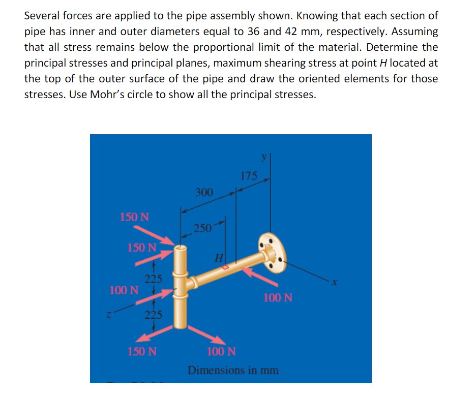

Transcribed Image Text:Several forces are applied to the pipe assembly shown. Knowing that each section of
pipe has inner and outer diameters equal to 36 and 42 mm, respectively. Assuming
that all stress remains below the proportional limit of the material. Determine the
principal stresses and principal planes, maximum shearing stress at point H located at
the top of the outer surface of the pipe and draw the oriented elements for those
stresses. Use Mohr's circle to show all the principal stresses.
175
300
150 N
250
150 N
H.
225
100 N
100 N
225
150 N
100 N
Dimensions in mm
Expert Solution
This question has been solved!
Explore an expertly crafted, step-by-step solution for a thorough understanding of key concepts.

This is a popular solution

Trending nowThis is a popular solution!

Step by stepSolved in 2 steps with 3 images

Knowledge Booster


Learn more about
Need a deep-dive on the concept behind this application? Look no further. Learn more about this topic, civil-engineering and related others by exploring similar questions and additional content below.Similar questions
- Please show all steps so your process is easy to followarrow_forwardSolve it correctly please. I will rate accordingly.arrow_forwardThe frame supports the distributed load shown. Determine the state of stress acting at point E. Show the results on a differential element at this point. The section is composed of two materials where E₁ = 200 GPa, and E₂ = 150 GPa AC xxxx E. 4 kN/m -1.5 m 1.5 m--- -3 m 3 m BA 20 mm 60 mm 20 mm 5 m E 50 mm E₁ = 200 GPa E₂ = 150 GPaarrow_forward
- The hollow circular beam is fixed to the wall (with a bracket) on the left and has an end-cap on the right. The cross-section is shown. (a) Determine state of stress at point A & draw the stress element (b) Determine state of stress at point B & draw the stress element A 100 k-in Tout 2 in n=1.75 in В. B 40 k-in C Tout 30 k Xarrow_forwardCalculate the design moment strength Mu for the following section. Take f'c = 40 MPa. Sketch the strain and stress distribution diagrams for each section and try to work out your solutions using equilibrium conditions. Yield stress for N bars is 500 MPa. 75 700 60 1500 T 4N28 450arrow_forward
arrow_back_ios
arrow_forward_ios
Recommended textbooks for you
 Structural Analysis (10th Edition)Civil EngineeringISBN:9780134610672Author:Russell C. HibbelerPublisher:PEARSON
 Principles of Foundation Engineering (MindTap Cou...Civil EngineeringISBN:9781337705028Author:Braja M. Das, Nagaratnam SivakuganPublisher:Cengage Learning
 Fundamentals of Structural AnalysisCivil EngineeringISBN:9780073398006Author:Kenneth M. Leet Emeritus, Chia-Ming Uang, Joel LanningPublisher:McGraw-Hill Education
 Traffic and Highway EngineeringCivil EngineeringISBN:9781305156241Author:Garber, Nicholas J.Publisher:Cengage Learning
Structural Analysis (10th Edition)
Civil Engineering
ISBN:9780134610672
Author:Russell C. Hibbeler
Publisher:PEARSON
Principles of Foundation Engineering (MindTap Cou...
Civil Engineering
ISBN:9781337705028
Author:Braja M. Das, Nagaratnam Sivakugan
Publisher:Cengage Learning
Fundamentals of Structural Analysis
Civil Engineering
ISBN:9780073398006
Author:Kenneth M. Leet Emeritus, Chia-Ming Uang, Joel Lanning
Publisher:McGraw-Hill Education
Traffic and Highway Engineering
Civil Engineering
ISBN:9781305156241
Author:Garber, Nicholas J.
Publisher:Cengage Learning