
Introductory Circuit Analysis (13th Edition)
13th Edition
ISBN: 9780133923605
Author: Robert L. Boylestad
Publisher: PEARSON
expand_more
expand_more
format_list_bulleted
Related questions
Question
Second half lab procedures continued.
3.Using Matlab code in Lab 2, set up the systems of Prelab 2(a) and Prelab 3, plot the step response of each of the 3 transfer functions on a single graph. Also, record the values of percent overshoot, settling time, peak time, and rise time for each step response.
4. Using Matlab code in Lab 2, set up the systems of Prelab 2(a) and Prelab 4, plot the step response of each of the 3 transfer functions on a single graph. Also, record the values of percent overshoot, settling time, peak time, and rise time for each step response.
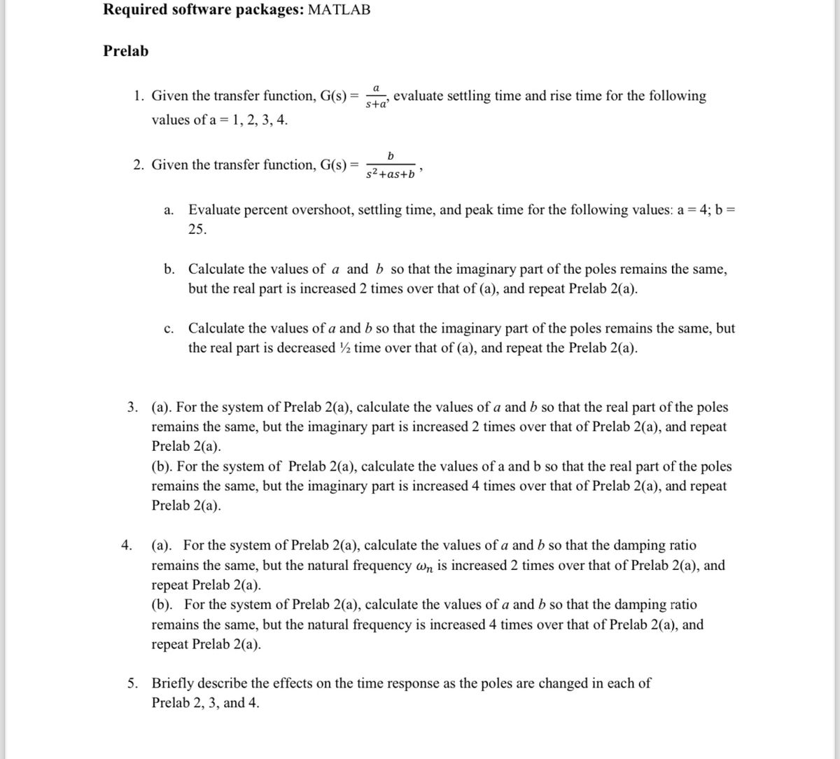

Transcribed Image Text:Required software packages: MATLAB
Prelab
1. Given the transfer function, G(s) =
values of a 1, 2, 3, 4.
2. Given the transfer function, G(s) =
4.
a
s+a'
evaluate settling time and rise time for the following
C.
b
s²+as+b
a. Evaluate percent overshoot, settling time, and peak time for the following values: a = 4; b =
25.
b. Calculate the values of a and b so that the imaginary part of the poles remains the same,
but the real part is increased 2 times over that of (a), and repeat Prelab 2(a).
Calculate the values of a and b so that the imaginary part of the poles remains the same, but
the real part is decreased ½ time over that of (a), and repeat the Prelab 2(a).
3. (a). For the system of Prelab 2(a), calculate the values of a and b so that the real part of the poles
remains the same, but the imaginary part is increased 2 times over that of Prelab 2(a), and repeat
Prelab 2(a).
(b). For the system of Prelab 2(a), calculate the values of a and b so that the real part of the poles
remains the same, but the imaginary part is increased 4 times over that of Prelab 2(a), and repeat
Prelab 2(a).
(a). For the system of Prelab 2(a), calculate the values of a and b so that the damping ratio
remains the same, but the natural frequency wn is increased 2 times over that of Prelab 2(a), and
repeat Prelab 2(a).
(b). For the system of Prelab 2(a), calculate the values of a and b so that the damping ratio
remains the same, but the natural frequency is increased 4 times over that of Prelab 2(a), and
repeat Prelab 2(a).
5. Briefly describe the effects on the time response as the poles are changed in each of
Prelab 2, 3, and 4.
![Lab Procedures
1. Using following Matlab code, set up the systems of Prelab 1 and plot the step response of each of
the 4 transfer functions on a single. Also, record the values of settling time and rise time for each
step response by observing.
num1 = 1;
den1 [1 1];
T1 tf (numl, den1)
num2=2;
den2= [1 2];
T2=tf (num2, den2)
num3=3;
den3= [13];
T3 tf (num3, den3)
num4=4;
den 4= [1 4];
T4=tf(num4, den4)
step (T1, T2, T3, T4)
2. Using following Matlab code, set up the systems of Prelab 2, plot the step response of each of the
3 transfer functions on a single graph. Also, record the values of percent overshoot, settling time,
peak time, and rise time for each step response.
num1=25;
den1= [1 4 25];
T1=tf (num1, den 1)
num2=b;
den2= [1 a b];
T2=tf (num2, den2)
num3=b;
den3= [1 a b];
T3=tf (num3, den3)
step (T1, T2, T3)
Calculate new b
% Calculate new a
Calculate new b
Calculate new a](https://content.bartleby.com/qna-images/question/5511825b-58e7-463e-a5dc-1d8731c21fdc/70243fc6-656c-4c08-bd3d-7dcdc0eca8a2/vc4l6gr_processed.jpeg)
Transcribed Image Text:Lab Procedures
1. Using following Matlab code, set up the systems of Prelab 1 and plot the step response of each of
the 4 transfer functions on a single. Also, record the values of settling time and rise time for each
step response by observing.
num1 = 1;
den1 [1 1];
T1 tf (numl, den1)
num2=2;
den2= [1 2];
T2=tf (num2, den2)
num3=3;
den3= [13];
T3 tf (num3, den3)
num4=4;
den 4= [1 4];
T4=tf(num4, den4)
step (T1, T2, T3, T4)
2. Using following Matlab code, set up the systems of Prelab 2, plot the step response of each of the
3 transfer functions on a single graph. Also, record the values of percent overshoot, settling time,
peak time, and rise time for each step response.
num1=25;
den1= [1 4 25];
T1=tf (num1, den 1)
num2=b;
den2= [1 a b];
T2=tf (num2, den2)
num3=b;
den3= [1 a b];
T3=tf (num3, den3)
step (T1, T2, T3)
Calculate new b
% Calculate new a
Calculate new b
Calculate new a
Expert Solution
This question has been solved!
Explore an expertly crafted, step-by-step solution for a thorough understanding of key concepts.

This is a popular solution

Trending nowThis is a popular solution!

Step by stepSolved in 5 steps with 2 images

Knowledge Booster


Learn more about
Need a deep-dive on the concept behind this application? Look no further. Learn more about this topic, electrical-engineering and related others by exploring similar questions and additional content below.Similar questions
- How to tell the difference between a open loop transfer function and closed loop transfer function?arrow_forward4. a) Based on non-linear circuits: i) Draw a block diagram representing a general oscillator. ii) State the Barkhausen Criterion. b) Consider the Schmitt trigger circuit shown in Figure Q4(a) where the comparator output saturation voltages are given as Vm+ = +15V and Vm- = -12V. R₁ Vow VR R₂ www R₁ Figure Q4(a) i) Calculate the upper and lower threshold voltages at Va if R₁ = 10 k2, R₂ = 20 kn and VR = 3V. ii) Compute the hysteresis voltage, VH. iii) Sketch the transfer characteristics (V₁ vs Va). c) Consider the oscillator shown in Figure Q4(b). i) Name the oscillator type. ii) Deduce the oscillation frequency equation. R₂ Vb Figure Q4(b) V out Z₁arrow_forwardGive an example of an analogue device that can be used as a phase comparator in a PLL system and explain its operation.arrow_forward
arrow_back_ios
arrow_forward_ios
Recommended textbooks for you
- Introductory Circuit Analysis (13th Edition)Electrical EngineeringISBN:9780133923605Author:Robert L. BoylestadPublisher:PEARSON
 Delmar's Standard Textbook Of ElectricityElectrical EngineeringISBN:9781337900348Author:Stephen L. HermanPublisher:Cengage Learning
 Programmable Logic ControllersElectrical EngineeringISBN:9780073373843Author:Frank D. PetruzellaPublisher:McGraw-Hill Education
  Fundamentals of Electric CircuitsElectrical EngineeringISBN:9780078028229Author:Charles K Alexander, Matthew SadikuPublisher:McGraw-Hill Education
 Electric Circuits. (11th Edition)Electrical EngineeringISBN:9780134746968Author:James W. Nilsson, Susan RiedelPublisher:PEARSON
 Engineering ElectromagneticsElectrical EngineeringISBN:9780078028151Author:Hayt, William H. (william Hart), Jr, BUCK, John A.Publisher:Mcgraw-hill Education,
Introductory Circuit Analysis (13th Edition)
Electrical Engineering
ISBN:9780133923605
Author:Robert L. Boylestad
Publisher:PEARSON
Delmar's Standard Textbook Of Electricity
Electrical Engineering
ISBN:9781337900348
Author:Stephen L. Herman
Publisher:Cengage Learning
Programmable Logic Controllers
Electrical Engineering
ISBN:9780073373843
Author:Frank D. Petruzella
Publisher:McGraw-Hill Education
Fundamentals of Electric Circuits
Electrical Engineering
ISBN:9780078028229
Author:Charles K Alexander, Matthew Sadiku
Publisher:McGraw-Hill Education
Electric Circuits. (11th Edition)
Electrical Engineering
ISBN:9780134746968
Author:James W. Nilsson, Susan Riedel
Publisher:PEARSON
Engineering Electromagnetics
Electrical Engineering
ISBN:9780078028151
Author:Hayt, William H. (william Hart), Jr, BUCK, John A.
Publisher:Mcgraw-hill Education,