Structural Analysis
6th Edition
ISBN: 9781337630931
Author: KASSIMALI, Aslam.
Publisher: Cengage,
expand_more
expand_more
format_list_bulleted
Question

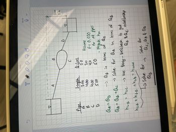
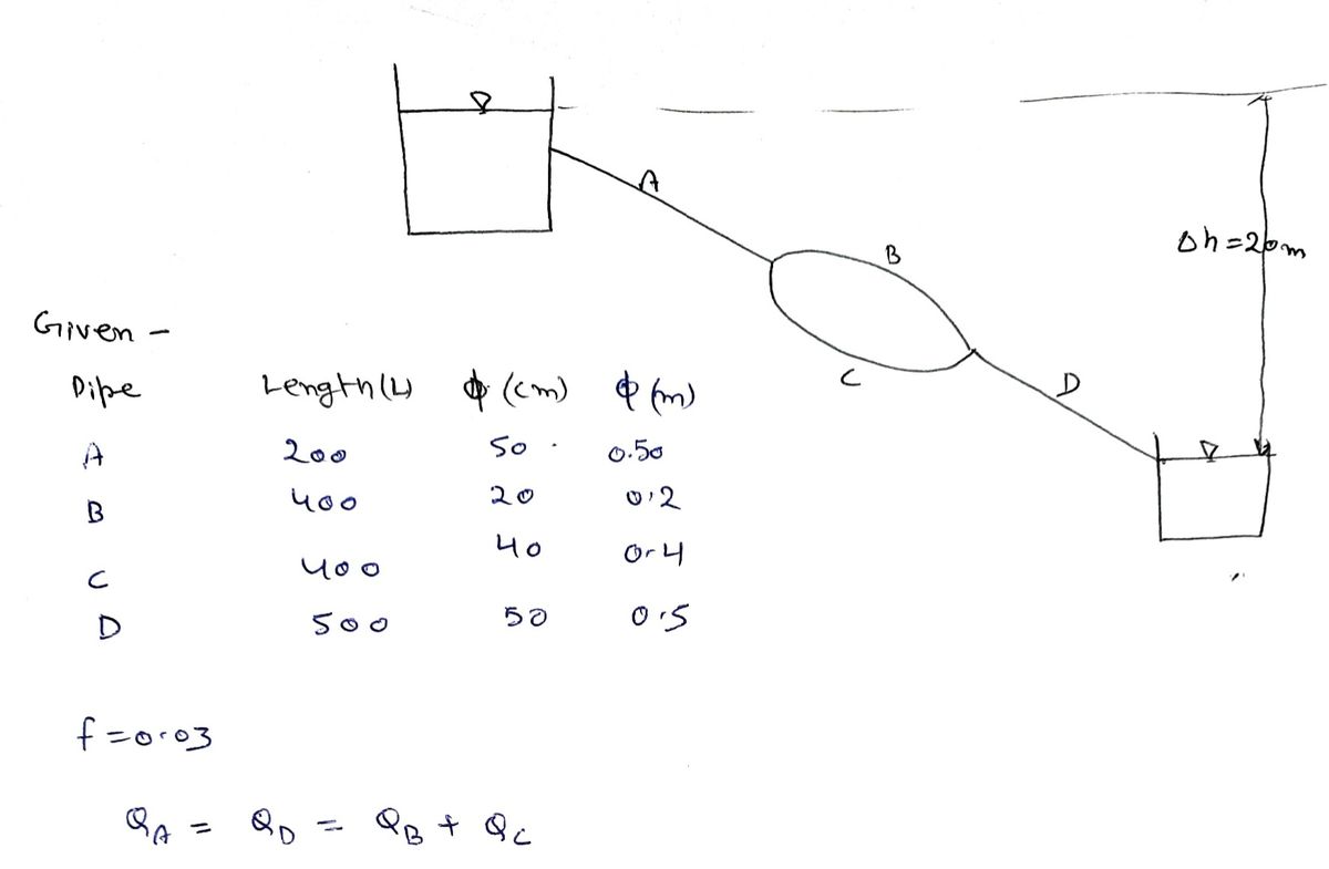
Transcribed Image Text:## Pipe Flow Analysis
This image illustrates a network of pipes and demonstrates methods for analyzing fluid flow within the system. Below is a detailed transcription and explanation:
### Diagram Explanation
The diagram features a schematic representation of a pipe system, consisting of four different pipes (A, B, C, and D) with specified lengths and diameters:
- **Pipe A**: Length = 200, Diameter = 50 cm
- **Pipe B**: Length = 400, Diameter = 40 cm
- **Pipe C**: Length = 400, Diameter = 20 cm
- **Pipe D**: Length = 500, Diameter = 50 cm
Two reservoirs are depicted at either end of the pipe network, with a height difference of 20 meters, indicated as \( \Delta h = 20m \).
### Assumptions
- Friction factor, \( f = 0.030 \) for all pipes.
- Neglect minor losses.
### Mathematical Equations and Approach
1. **Flow Equations**:
- \( Q_A = Q_D \)
- Express \( Q_D \) in terms of \( Q_B \).
2. **Continuity Equation**:
- \( Q_A = Q_B + Q_C \)
- Use the Darcy-Weisbach equation to establish a relationship between \( Q_B \) and \( Q_C \).
3. **Head Loss Equations**:
- \( h_{LB} = h_{LC} \)
- Total head loss: \( h_{LA} + h_{LB} + h_{LD} = h_{total} \)
4. **Solution Approach**:
- Solve for \( Q_B \).
- Subsequently, solve for \( Q_A, Q_B, \) and \( Q_D \).
This analysis involves applying fluid mechanics principles to determine flow rates and the distribution of head loss across different sections of the pipe network. By using the given pipe dimensions, friction factor, and assumptions, engineers can solve for flow variables and optimize the design of the system.
Expert Solution
arrow_forward
Step 1

Step by stepSolved in 4 steps with 3 images

Knowledge Booster
Learn more about
Need a deep-dive on the concept behind this application? Look no further. Learn more about this topic, civil-engineering and related others by exploring similar questions and additional content below.Similar questions
- Please write the solution on paper.arrow_forwardThe 22-mm-diameter A-36 steel rod is subjected to the axial forces shown. Take E = 200 GPa. (Figure 1) Figure 1 A of 1 600 mm B 400 mm 50 kN 50 kN C 40 kN MILA Determine the displacement of end C with respect to the fixed support at A. Express your answer to three significant figures and include the appropriate units. 1 dc = Submit μÅ Value Units My Answers Give Up ?arrow_forward2. Given the equations from Joint B Solve for the force in BD and BE. 600 lb 600 lb 600 lb 600 lb BD D 300 lb B. F 2 ft 4 in. 300 lb| 6 ft 1500 lb ВЕ E G H. 8 ft 8 ft→-8 ft→-8 ft 8. BD 8. ΣΕ-0= 1500| 8. BE 10 10 6. = 0 =1500 10 1, 600 – BD 8 6. + BE 10 3. Solve for x and y. 1200 lb 30°arrow_forward
arrow_back_ios
arrow_forward_ios
Recommended textbooks for you

 Structural Analysis (10th Edition)Civil EngineeringISBN:9780134610672Author:Russell C. HibbelerPublisher:PEARSON
 Principles of Foundation Engineering (MindTap Cou...Civil EngineeringISBN:9781337705028Author:Braja M. Das, Nagaratnam SivakuganPublisher:Cengage Learning
 Fundamentals of Structural AnalysisCivil EngineeringISBN:9780073398006Author:Kenneth M. Leet Emeritus, Chia-Ming Uang, Joel LanningPublisher:McGraw-Hill Education
 Traffic and Highway EngineeringCivil EngineeringISBN:9781305156241Author:Garber, Nicholas J.Publisher:Cengage Learning


Structural Analysis (10th Edition)
Civil Engineering
ISBN:9780134610672
Author:Russell C. Hibbeler
Publisher:PEARSON

Principles of Foundation Engineering (MindTap Cou...
Civil Engineering
ISBN:9781337705028
Author:Braja M. Das, Nagaratnam Sivakugan
Publisher:Cengage Learning

Fundamentals of Structural Analysis
Civil Engineering
ISBN:9780073398006
Author:Kenneth M. Leet Emeritus, Chia-Ming Uang, Joel Lanning
Publisher:McGraw-Hill Education


Traffic and Highway Engineering
Civil Engineering
ISBN:9781305156241
Author:Garber, Nicholas J.
Publisher:Cengage Learning