Introductory Circuit Analysis (13th Edition)
13th Edition
ISBN: 9780133923605
Author: Robert L. Boylestad
Publisher: PEARSON
expand_more
expand_more
format_list_bulleted
Concept explainers
Question
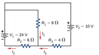
Consider the circuit shown below. Find I1, I2 and I3.

Transcribed Image Text:R, = 8 N
V2 = 10 V
:V, = 24 V
R2 = 6 N
R3 = 4 N
12
13
Expert Solution
This question has been solved!
Explore an expertly crafted, step-by-step solution for a thorough understanding of key concepts.
This is a popular solution
Trending nowThis is a popular solution!
Step by stepSolved in 3 steps

Knowledge Booster
Learn more about
Need a deep-dive on the concept behind this application? Look no further. Learn more about this topic, electrical-engineering and related others by exploring similar questions and additional content below.Similar questions
- a) Consider the DC circuit below. Use the principle of Superposition to determine the following circuit parameters: i. The current through R1 ii. The voltage across R1 iii. The current through R3 iv. The voltage across R3 v. The voltage across R2 vi. The power dissipated in R2 Please answer all subpart either dislike is ready Please answer in typing format please ASAP for the likearrow_forwardQuestion vvvv Full explain this question and text typing work only We should answer our question within 2 hours takes more time then we will reduce Rating Dont ignore this line ..arrow_forward(b) Consider the network shown in Figure Q2b, where the numbers indicate admittances. The shunt elements all have positive susceptance, and must therefore be capacitive. 11) Write the current injections at each busbar using Kirchoff's Current Law (KCL). Construct the admittance matrix (Y) of the network. bus 1 2-14 1-14 bus 2 j0.2 2-15 bus 3 j0.3 Figure Q2b 2-3 bus 4arrow_forward
- Can someone help me, thank you!arrow_forwardA series circuit has a total resistance of 19 ohms and a current flow of 12 A. What is the applied voltage? Select one: a. 1.583 b. .631 c. 228 d. 410arrow_forward2. In the circuit of Figure below is1 = Vs2=0, Vs1 = 9 V, İs2 = 12 A. For the four cases of (a) R = 0, (b) R=60,(c) R = 90 and (d) R = 10,0000 draw the simplified circuit and find IBA and VAC. Hint: A zero voltage source corresponds to a short-circuited element and a zero current source corresponds to an open-circuited element. İBA B A ww R VS₂ 3 Ω 6Ω U SVarrow_forward
- Consider the following resistor network: i₁ = E A, 1₂ = Voltage gain across I is b. Report the voltage gain across the current source I. (Click on the image to enlarge) Suppose R₁ = 60, R₂ = 50, R3 = 142, R₁ = 4, R5 = 4N, E = 28V and I = 6A. Set up and solve a linear system for the loop currents and the voltage across the current source as shown in the online notes. a. Report the loop currents i1, 12 and i3 (positive for clockwise direction). V R₁ A, 23 = R₂. R3 R4 A R5arrow_forwardSolve asaparrow_forwardThe current flowing in resistor R in the circuit shown in figure is I2- I1. See the Pic and Select one: a) True b) Falsearrow_forward
- For the circuit shown, select the values of R1, R2 & R3 so that: y11=0.006 mho, y12 =y21=-0.001 mho & y22=0.003 mho I R2 I2 V1 R1 R3 V2 400 ohm, 500 ohm, and 200 ohm 200 ohm, 400 ohm, and 500 ohm 200 ohm, 1000 ohm, and 500 ohm 400 ohm, 1000 ohm, and 400 ohmarrow_forwardConsirder the circuit diagram below. Given I1 = 2 mA and I4= 6mA, find the currents I2, I3, I5 and I6. State your conclusion as a table of values.arrow_forwardLO: 1, 2, 4,5,6: Figure shows the resistors from the previous two examples wired in a differentway—a combination of series and parallel. We can consider R1 to be the resistance of wiresleading to R2 and R3. (a) Find the total resistance. (b) What is the IR drop in R1? (c) Find thecurrent I2 through R2. (d) What power is dissipated by R2?arrow_forward
arrow_back_ios
SEE MORE QUESTIONS
arrow_forward_ios
Recommended textbooks for you
 Introductory Circuit Analysis (13th Edition)Electrical EngineeringISBN:9780133923605Author:Robert L. BoylestadPublisher:PEARSON
 Delmar's Standard Textbook Of ElectricityElectrical EngineeringISBN:9781337900348Author:Stephen L. HermanPublisher:Cengage Learning
 Programmable Logic ControllersElectrical EngineeringISBN:9780073373843Author:Frank D. PetruzellaPublisher:McGraw-Hill Education
 Fundamentals of Electric CircuitsElectrical EngineeringISBN:9780078028229Author:Charles K Alexander, Matthew SadikuPublisher:McGraw-Hill Education
 Electric Circuits. (11th Edition)Electrical EngineeringISBN:9780134746968Author:James W. Nilsson, Susan RiedelPublisher:PEARSON
 Engineering ElectromagneticsElectrical EngineeringISBN:9780078028151Author:Hayt, William H. (william Hart), Jr, BUCK, John A.Publisher:Mcgraw-hill Education,

Introductory Circuit Analysis (13th Edition)
Electrical Engineering
ISBN:9780133923605
Author:Robert L. Boylestad
Publisher:PEARSON

Delmar's Standard Textbook Of Electricity
Electrical Engineering
ISBN:9781337900348
Author:Stephen L. Herman
Publisher:Cengage Learning

Programmable Logic Controllers
Electrical Engineering
ISBN:9780073373843
Author:Frank D. Petruzella
Publisher:McGraw-Hill Education

Fundamentals of Electric Circuits
Electrical Engineering
ISBN:9780078028229
Author:Charles K Alexander, Matthew Sadiku
Publisher:McGraw-Hill Education

Electric Circuits. (11th Edition)
Electrical Engineering
ISBN:9780134746968
Author:James W. Nilsson, Susan Riedel
Publisher:PEARSON

Engineering Electromagnetics
Electrical Engineering
ISBN:9780078028151
Author:Hayt, William H. (william Hart), Jr, BUCK, John A.
Publisher:Mcgraw-hill Education,