Introductory Circuit Analysis (13th Edition)
13th Edition
ISBN: 9780133923605
Author: Robert L. Boylestad
Publisher: PEARSON
expand_more
expand_more
format_list_bulleted
Question
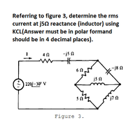
Referring to figure 3, determine the rms current at j5Ω reactance (inductor) using KCL(Answer must be in polar formand should be in 4 decimal places).

Transcribed Image Text:Referring to figure 3, determine the rms
current at j50 reactance (inductor) using
KCL(Answer must be in polar formand
should be in 4 decimal places).
4 0
-is n
-j8 N
6 0
js n
| 220/– 30° V
Figure 3.
Expert Solution
This question has been solved!
Explore an expertly crafted, step-by-step solution for a thorough understanding of key concepts.
Step by stepSolved in 2 steps with 2 images

Knowledge Booster
Learn more about
Need a deep-dive on the concept behind this application? Look no further. Learn more about this topic, electrical-engineering and related others by exploring similar questions and additional content below.Similar questions
- Refer to Figure If 50V is applied across the capacitors, determine Q. Write the answer in mC 30 μF 60 µF 20 µF ▬HE HE C₁ C2 C 3 -arrow_forwardIf three inductors connected in series 0.06 H,0.05H,0.1H.What would be the inductive reactance of the circuit?Assume The inductors are connected to a 60Hz line?arrow_forwardA voltage waveform is shown below, please find its RMS voltage value. Choose the value that is closest to the answer. NEED A NEAT HAND WRITING ONLY OTHERWISE WILL LEAVE A DOWNVOTE NO CHAT GPT MINIMUM3 STEPS WITH EXPLANATIONarrow_forward
- Please answer in typing format solution please only Please answer in typing format I will like it please thanks pleasearrow_forwardDesign a circuit to limit a 20 V rms sinusoidal voltage to a maximum positive amplitude of 10 V and a maximum negative amplitude of -5 Vusing a single 14 V dc voltage sourcearrow_forward1) Two identical voltage waveforms of difference phase angles are shown in Figure B. Write down the expression of waveforms A and B clearly. HUS Voltage (V) 8 0 K/N B 7: ST otarrow_forward
- Capscitor questionarrow_forwardQ4. Determine the equivalent inductance and equivalent current of the inductive circuit in Figure Q4. If Ls is replaced with a capacitor of 0.55 mF, how would it affect the branch current? The alternating Voltage source has an amplitude of 25 Vm. Vm Sine 55 Hz L1 5 mH L2 5.3 mH rele cele Figure Q4 000 ele L3 6.6 mH L4 8.3 mH cele L5 7.7 mHarrow_forwardExplain why voltage spikes and surges are high frequency occurencesarrow_forward
arrow_back_ios
arrow_forward_ios
Recommended textbooks for you
 Introductory Circuit Analysis (13th Edition)Electrical EngineeringISBN:9780133923605Author:Robert L. BoylestadPublisher:PEARSON
 Delmar's Standard Textbook Of ElectricityElectrical EngineeringISBN:9781337900348Author:Stephen L. HermanPublisher:Cengage Learning
 Programmable Logic ControllersElectrical EngineeringISBN:9780073373843Author:Frank D. PetruzellaPublisher:McGraw-Hill Education
 Fundamentals of Electric CircuitsElectrical EngineeringISBN:9780078028229Author:Charles K Alexander, Matthew SadikuPublisher:McGraw-Hill Education
 Electric Circuits. (11th Edition)Electrical EngineeringISBN:9780134746968Author:James W. Nilsson, Susan RiedelPublisher:PEARSON
 Engineering ElectromagneticsElectrical EngineeringISBN:9780078028151Author:Hayt, William H. (william Hart), Jr, BUCK, John A.Publisher:Mcgraw-hill Education,

Introductory Circuit Analysis (13th Edition)
Electrical Engineering
ISBN:9780133923605
Author:Robert L. Boylestad
Publisher:PEARSON

Delmar's Standard Textbook Of Electricity
Electrical Engineering
ISBN:9781337900348
Author:Stephen L. Herman
Publisher:Cengage Learning

Programmable Logic Controllers
Electrical Engineering
ISBN:9780073373843
Author:Frank D. Petruzella
Publisher:McGraw-Hill Education

Fundamentals of Electric Circuits
Electrical Engineering
ISBN:9780078028229
Author:Charles K Alexander, Matthew Sadiku
Publisher:McGraw-Hill Education

Electric Circuits. (11th Edition)
Electrical Engineering
ISBN:9780134746968
Author:James W. Nilsson, Susan Riedel
Publisher:PEARSON

Engineering Electromagnetics
Electrical Engineering
ISBN:9780078028151
Author:Hayt, William H. (william Hart), Jr, BUCK, John A.
Publisher:Mcgraw-hill Education,