
Elements Of Electromagnetics
7th Edition
ISBN: 9780190698614
Author: Sadiku, Matthew N. O.
Publisher: Oxford University Press
expand_more
expand_more
format_list_bulleted
Related questions
Question

Transcribed Image Text:Fig. 9-36
A.
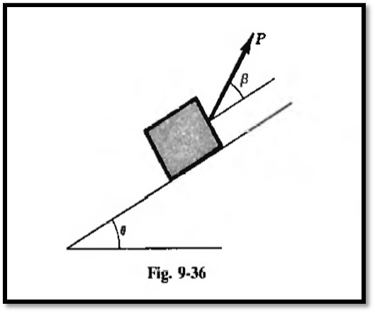
![Refer to Fig. 9-36. The angle of static friction between the block with mass M and the plane is d. For the
angles shown in the figure, what is the expression for the force P to move the block up the plane?
Ans. P= [9.8M sin (0 + 4)}/[cos (ß – 4)]](https://content.bartleby.com/qna-images/question/88481529-9034-44cc-a131-5d7db059788e/003d8315-1610-4db3-a3c2-681fea22b35a/7opvpx_processed.jpeg)
Transcribed Image Text:Refer to Fig. 9-36. The angle of static friction between the block with mass M and the plane is d. For the
angles shown in the figure, what is the expression for the force P to move the block up the plane?
Ans. P= [9.8M sin (0 + 4)}/[cos (ß – 4)]
Expert Solution
This question has been solved!
Explore an expertly crafted, step-by-step solution for a thorough understanding of key concepts.

Step by stepSolved in 2 steps with 2 images

Knowledge Booster


Learn more about
Need a deep-dive on the concept behind this application? Look no further. Learn more about this topic, mechanical-engineering and related others by exploring similar questions and additional content below.Similar questions
- Figure The figure shows a schematic of an engine. F, is the force exerted by the combustion gases on the piston (shown by the rectangle at B). FÅ= 50 kN. The angle of the crank OA is 0 = 30° while the angle of the connecting rod AB is p = 15°. Neglect the weight of all members. Also neglect friction between the piston and the cylinder. A 30 cm 10 cm B Fg 0 M₂arrow_forwardFluidsarrow_forwardThe simple truss is loaded by a system of forces as shown in the figure. The truss is supported by a pin at A and a roller at E. If P1 = 40 [KN] and P2 = 20 [KN], then the force developed in the member (EF) is. B 2 m A F F1.5 m--1.5 m-1.5 m--1.5 m-| P2 Select one: a. 18.75 kN - Tension b. 78.15 kN - Compression c. 51.78 kN - Tension d. 17.85 kN - Tensionarrow_forward
- Select all statements that can be applied to the Machine shown in the figure (a) True False Or Neither true or falsearrow_forwardThe figure on the left, below, shows a non-uniform bent rod with a mass of 5 kg. Your job is to determine the location of the center of gravity of this rod. You design an experiment: you connect a pin and cable to the rod such that it safely stays in static equilibrium under a force P that you apply. Then, you apply forces between 0-100 N, and measure the tension force on the cable using a cable tension meter. The results of your experiment are shown in the figure, on the right. Using this experiment, calculate (approximately) the horizontal distance (x in the figure) between point A and the center of gravity G of the bent rod. B C O I 20 cm 20 cm 60° D 50 cm Tension measurement [N] 60 50 40 30 20 -10 0 10 real data estimated fit 20 30 40 ܐܐܝ 50 P[N] 60 70 80 90 100arrow_forward600 N 4 m 900 N E 4 m В A 6 m What is the force in the member [CB]? İs it tension or compression?arrow_forward
- Figure The figure shows a schematic of an engine. F, is the force exerted by the combustion gases on the piston (shown by the rectangle at B). FÅ= 50 kN. The angle of the crank OA is 0 = 30° while the angle of the connecting rod AB is p = 15°. Neglect the weight of all members. Also neglect friction between the piston and the cylinder. A 30 cm 10 cm B Fg 0 M₂arrow_forwardThe[m2]-kg block shown sits on top of a[m1]-kg ramp,which is being pushed by an external forceP.Thecoefficients of static and kinetic frictions between the rampand block are[μs]and 0.2 respectively. The ramp is onrollers and we can assume its contact with the ground isfrictionless. ForcePis always applied in the direction shown.(a) Calculate the minimum forcePrequired to keep the block from sliding on the ramp.(b) Calculate the maximum forcePthat can be applied before the block slides on the ramp.arrow_forwardGiven the 600-N force applied to the bracket at A in Fig 1 below, determine: (a) the horizontal and vertical components, label as Fx and Fy respectively. Clearly draw the resolution process to get these components and indicate the axes. (b) the components that are parallel and perpendicular to the direction 150 W of N. Label the components as F1 and F2 respectively. Clearly draw the resolution process to get these components and indicate the axes. (c) the components that are parallel and perpendicular to the direction 150S of E. Label these components as F3 and F4 respectively. Clearly draw the resolution process to get these components and indicate the axes.arrow_forward
arrow_back_ios
arrow_forward_ios
Recommended textbooks for you
- Elements Of ElectromagneticsMechanical EngineeringISBN:9780190698614Author:Sadiku, Matthew N. O.Publisher:Oxford University Press
 Mechanics of Materials (10th Edition)Mechanical EngineeringISBN:9780134319650Author:Russell C. HibbelerPublisher:PEARSON
 Thermodynamics: An Engineering ApproachMechanical EngineeringISBN:9781259822674Author:Yunus A. Cengel Dr., Michael A. BolesPublisher:McGraw-Hill Education
  Control Systems EngineeringMechanical EngineeringISBN:9781118170519Author:Norman S. NisePublisher:WILEY
 Mechanics of Materials (MindTap Course List)Mechanical EngineeringISBN:9781337093347Author:Barry J. Goodno, James M. GerePublisher:Cengage Learning
 Engineering Mechanics: StaticsMechanical EngineeringISBN:9781118807330Author:James L. Meriam, L. G. Kraige, J. N. BoltonPublisher:WILEY
Elements Of Electromagnetics
Mechanical Engineering
ISBN:9780190698614
Author:Sadiku, Matthew N. O.
Publisher:Oxford University Press
Mechanics of Materials (10th Edition)
Mechanical Engineering
ISBN:9780134319650
Author:Russell C. Hibbeler
Publisher:PEARSON
Thermodynamics: An Engineering Approach
Mechanical Engineering
ISBN:9781259822674
Author:Yunus A. Cengel Dr., Michael A. Boles
Publisher:McGraw-Hill Education
Control Systems Engineering
Mechanical Engineering
ISBN:9781118170519
Author:Norman S. Nise
Publisher:WILEY
Mechanics of Materials (MindTap Course List)
Mechanical Engineering
ISBN:9781337093347
Author:Barry J. Goodno, James M. Gere
Publisher:Cengage Learning
Engineering Mechanics: Statics
Mechanical Engineering
ISBN:9781118807330
Author:James L. Meriam, L. G. Kraige, J. N. Bolton
Publisher:WILEY