Question
Hello,
I need help filling out the table and calculating for D.
Thanks.

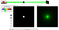
Transcribed Image Text:0.1 mm
10 mm
Wavelength
511 nm
Diameter
0 10 mm
Eccentricity
0.00

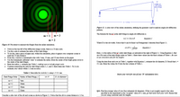
Transcribed Image Text:radius
mth order
dark fringe
slit
L-10 m
sereen
Figure 11: A side-view of the online simulation, defining the geometry used to analyze single-slit diffaction
patterns.
The formula for the morder dark fringe in single-slit difiraction is
m = 1
m = 3
mi = Dsine
Equation 1
m = 2
Where D is the slit width. Notice that e can be found via Pythagorean's theorem from Figure 11.
Figure 10. Procedure to measure the fringes from the online simulation.
sin 8 =
Equation 2
• Notice at the top left of the diffaction image screen, there is a 10 mm scale.
• Use this scale to estimate the radius of first dark fringe.
• To do this, take a piece of paper and, within the simulation, place it against your computer screen to
Here, y is the radius of the mt order dark fringe, as indicated at the right of Figure 11. Using Equation 2, find
sin e for each of the dark fringe orders in Table 1. Enter these values into the third column of Table 1. Be surs
to use consistent wnits for the lengths!
mark the 10 mm distance.
• From this, construct a homemade ruler with 5 mm, 10 mm, and 20 mm drawn on the paper.
• Use this homemade calibrated 'ruler' to estimate the radius (from the center of the bright green circle to
the center of the dark fringe).
• Enter the radius, y, estimate into Table 1, making sure to include proper wnits.
• Continue measuring the radii for dark fringe orders 2, 3, and 4. Enter them into Table 1. Try to do
estimate your values within 1-2 mm accuracy.
Using the data from each row in Table 1, together with Equation 1, estimate the slit diameter, D. Recall that 2 =
511 nm. Enter the values for D into the last column of Table 1.
Table 1: Data table for Activity 2, using 2 = 511 nm.
Insert yowr work for one of your 'D' calculations here.
Dark Fringe Order
Radius of Dark Fringe, y
sin e
D, slit dianeter
m=1
7mm
m =2
14mm
m =3
18mm
m=4
22mm
Q11. Find the average value of your four estimated slit diameters. If this is not roughly equal to the value
specified in the experiment as the 'accepted' value of 0.l mm, go back and check your work Ensure that
you are using consistent units for lengths.
Consider a side-view of the slit and screen as showm in Figure 11. Notice that the slit to screen distance is 1.0 m.
Expert Solution
This question has been solved!
Explore an expertly crafted, step-by-step solution for a thorough understanding of key concepts.
This is a popular solution
Trending nowThis is a popular solution!
Step by stepSolved in 3 steps

Knowledge Booster
Similar questions
- A map suggests that Atlanta is 730. miles in a direction 5.00°north of east from Dallas. The same map shows that Chicagois 560. miles in a direction 21.0° west of north from Atlanta.Figure P1.68 shows the location of these three cities. Modelingthe Earth as flat, use this information to find the displacementfrom Dallas to Chicago.arrow_forwardVector A = 7.4 i + 3.2 j. Vector B = 3.7 i - 7.1 j. Calculate the angle between the two vectors in degrees.arrow_forward