Introductory Circuit Analysis (13th Edition)
13th Edition
ISBN: 9780133923605
Author: Robert L. Boylestad
Publisher: PEARSON
expand_more
expand_more
format_list_bulleted
Question

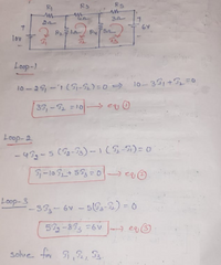
Transcribed Image Text:R1
Rs
Rs
GV
lov
Loop-)
10 -29, -'1 (5-2) =0 =) 1lo-39,+T=0
39,- =10- e
Loop-2
- 43g-5 (g-P) –1(5-5)= 0
Loop-3
-333-6v - 5(G3-2) = 0
5-873 =6V- e
solve for ,2, S3.
Expert Solution
This question has been solved!
Explore an expertly crafted, step-by-step solution for a thorough understanding of key concepts.
Step by stepSolved in 3 steps with 3 images

Knowledge Booster
Learn more about
Need a deep-dive on the concept behind this application? Look no further. Learn more about this topic, electrical-engineering and related others by exploring similar questions and additional content below.Similar questions
- A three way intersection is in need of a traffic signal control system and you have been assigned thetask to design and implement the system. Each direction has only one lane and one set of signalcontrol lights (green, yellow and red). Your design should only allow one go or green light at atime. Further, all transitions from green to red should go through an intermediate 2-4 secondsyellow light. and draw the design of the schematicarrow_forwardPlease see attached screen shot for questions a-f.arrow_forwardExplain diagramarrow_forward
- Shown in the figure below is an electrical circuit containing three resistors and two batteries. R3 10 R2 R1 Write down the Kirchhoff Junction equation and solve it for I, in terms of I, and Iz. Write the result here: Write down the Kirchhoff Loop equation for a loop that starts at the lower left corner and follows the perimeter of the circuit diagram clockwise. Write down the Kirchhoff Loop equation for a loop that starts at the lower left corner and touches the components R1, R2, and 4V. The resistors in the circuit have the following values: R, = 130 • R2 = 50 R3 = 10 Solve for all the following (some answers may be negative): | Amperes I = I, = Amperes Iz = Amperes NOTE: For the equations, put in resistances and currents SYMBOLICALLY using variables like RR2,R3 and I,,12,13. Use numerical values of 10 and 4 for the voltages.arrow_forwardUse A-Y/ Y-A Transformation to solve for the (a) total resistance in terminals op (Rop) (b) total current. Voltage at terminal fe (Vfe) is 250 V. Show complete solution and redraw your transformations. 250 -M- 100 -25 100 -20 100 S00 40 -m 75 100 aniuearrow_forward
arrow_back_ios
arrow_forward_ios
Recommended textbooks for you
 Introductory Circuit Analysis (13th Edition)Electrical EngineeringISBN:9780133923605Author:Robert L. BoylestadPublisher:PEARSON
 Delmar's Standard Textbook Of ElectricityElectrical EngineeringISBN:9781337900348Author:Stephen L. HermanPublisher:Cengage Learning
 Programmable Logic ControllersElectrical EngineeringISBN:9780073373843Author:Frank D. PetruzellaPublisher:McGraw-Hill Education
 Fundamentals of Electric CircuitsElectrical EngineeringISBN:9780078028229Author:Charles K Alexander, Matthew SadikuPublisher:McGraw-Hill Education
 Electric Circuits. (11th Edition)Electrical EngineeringISBN:9780134746968Author:James W. Nilsson, Susan RiedelPublisher:PEARSON
 Engineering ElectromagneticsElectrical EngineeringISBN:9780078028151Author:Hayt, William H. (william Hart), Jr, BUCK, John A.Publisher:Mcgraw-hill Education,

Introductory Circuit Analysis (13th Edition)
Electrical Engineering
ISBN:9780133923605
Author:Robert L. Boylestad
Publisher:PEARSON

Delmar's Standard Textbook Of Electricity
Electrical Engineering
ISBN:9781337900348
Author:Stephen L. Herman
Publisher:Cengage Learning

Programmable Logic Controllers
Electrical Engineering
ISBN:9780073373843
Author:Frank D. Petruzella
Publisher:McGraw-Hill Education

Fundamentals of Electric Circuits
Electrical Engineering
ISBN:9780078028229
Author:Charles K Alexander, Matthew Sadiku
Publisher:McGraw-Hill Education

Electric Circuits. (11th Edition)
Electrical Engineering
ISBN:9780134746968
Author:James W. Nilsson, Susan Riedel
Publisher:PEARSON

Engineering Electromagnetics
Electrical Engineering
ISBN:9780078028151
Author:Hayt, William H. (william Hart), Jr, BUCK, John A.
Publisher:Mcgraw-hill Education,