
Mechanics of Materials (MindTap Course List)
9th Edition
ISBN: 9781337093347
Author: Barry J. Goodno, James M. Gere
Publisher: Cengage Learning
expand_more
expand_more
format_list_bulleted
Related questions
Question

Transcribed Image Text:r
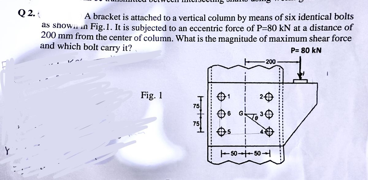
Q2.
A bracket is attached to a vertical column by means of six identical bolts
as shown in Fig. 1. It is subjected to an eccentric force of P-80 kN at a distance of
200 mm from the center of column. What is the magnitude of maximum shear force
and which bolt carry it?
P= 80 kN
200
Fig. 1
1
2-
75
6
30
75
→ 5
.5
1- 50 10-50-1
Expert Solution
This question has been solved!
Explore an expertly crafted, step-by-step solution for a thorough understanding of key concepts.

Step by stepSolved in 2 steps with 2 images

Knowledge Booster

Similar questions
- The assembly consists of three titanium (Ti-6A1- 4V) rods and a rigid bar AC. The cross-section area of each rod is given in the figure. If a force of 60 kip is applied o the ring F, determine the horizontal displacement of point F. Hint: Refer to the textbook appendix for material properties. AEF 2 in² 1 ft = 60 kip F-2 ft- 2 ft A C 6 ft B AAB = 1 in² E ACD = 1.5 in² 6 ft Darrow_forwardMechanics Of Materials Iarrow_forwardQuestion 1 A bracket is attached to a vertical column by means of six identical bolts as shown in Fig. It is subjected to an eccentric force of P = 30 kN at a distance of 200 mm from the center of the column. What is the magnitude of maximum shear force and which bolt carry it? 30 kN 200 mm 100 mm 150 mmarrow_forward
- Mechanics of materials Iarrow_forwardProblem 2. The assembly consists of three titanium (Ti- 6A1-4V) rods and a rigid bar AC. The cross-sectional area of each rod is given in the figure. If a force of 6 kip is applied to the ring F, determine the horizontal displacement of point F, and determine the angle of tilt of rigid bar AC. B D 4 ft ACD = 1 in² AAB 6 ft 1.5 in² E 2 ft 1 ft 1 ft AEF = 2 in² 6 kiparrow_forwardThe shaft is supported at its ends two bearings A and B and is subjected to the forces applied to the pulleys fixed to the shaft. (Figure 1) The T₁ = 410-N forces act in the -z direction and the 200-N and 80-N forces act in the +y direction. The journal bearings at A and B exert only y and components of force on the shaft. Figure 200 mm 300 mm 150 mm, 150 mm 200 mm 400 mm B 200 N 80 N 80 N 200 N < 1 of 1 Determine the resultant normal force on the cross section at C Express your answer to three significant figures and include appropriate units. Nc= Submit Part B (Vc)y= Submit Part C Value Determine the resultant shear force in the y direction on the cross section at C Express your answer to three significant figures and include appropriate units. (Vc)= = Request Answer 4 ▬▬ μÀ 4 Value Request Answer μà → ⒸIE ? Value Units Determine the resultant shear force in the direction on the cross section at C Express your answer to three significant figures and include appropriate units. Ć IE ?…arrow_forward
- Question 4: Two wrenches are used to tighten the pipe. If the pipe is made from a material having an allowable shear stress of Tallow = 85 MPa, check the allowable force for external and internal diameter of pipe and determine the allowable maximum force P that can be applied to each wrench. The pipe has an outer diameter of 25 mm and inner diameter of 20 mm. 250 mm B 250 mm Figure 4 Answer: Torque = 0.5P, Polar moment of inertial J = 2.26 x 10⁸ m4, outer diameter PS %3D 307.36N, inner diameter P S 384.2 N, Pallowable = 307.36Narrow_forwardDetermine the magnitude of the internal shear force experienced by pin B.arrow_forward2-12. For the truss shown in the figure, deter- mine the total elongation of the member BC due to the application of the force P = 450 kN. The || member BC is made from steel and is 60 mm² in cross-sectional area. E = 210 000 MN/m². %3| B 1.20 m D 450 kN 5 spaces at 0.90 m = 4.50 m %3Darrow_forward
- The rectangular bar is connected to the support bracket with a 24-mm-diameter pin. The bar width is w = 80 mm and the bar thickness is 20 mm. Each side of the bracket has the same dimensions as the bar. The average shear stress in the pin cannot exceed 125 MPa, the bearing stress in the bar cannot exceed 130 MPa, and the bearing stress in the bracket cannot exceed 130 MPa. Determine the maximum value of Pmax that can be supported by the structure. P Answer: Pmax =arrow_forwardThe three-bar truss in Fig. a is subjected to a horizontal force of 5 kip. If the cross-sectional area of each member is 0.20 in2, determine the horizontal displacement at point B. E = 29(103) ksi.arrow_forwardThe rectangular bar is connected to the support bracket with a 17-mm-diameter pin. The bar width is w = 70 mm and the bar thickness is 20 mm. Each side of the bracket has the same dimensions as the bar. The average shear stress in the pin cannot exceed 130 MPa, the bearing stress in the bar cannot exceed 140 MPa, and the bearing stress in the bracket cannot exceed 150 MPa. Determine the maximum value of Pmax that can be supported by the structure.arrow_forward
arrow_back_ios
SEE MORE QUESTIONS
arrow_forward_ios
Recommended textbooks for you
- Mechanics of Materials (MindTap Course List)Mechanical EngineeringISBN:9781337093347Author:Barry J. Goodno, James M. GerePublisher:Cengage Learning
Mechanics of Materials (MindTap Course List)
Mechanical Engineering
ISBN:9781337093347
Author:Barry J. Goodno, James M. Gere
Publisher:Cengage Learning