Structural Analysis
6th Edition
ISBN: 9781337630931
Author: KASSIMALI, Aslam.
Publisher: Cengage,
expand_more
expand_more
format_list_bulleted
Question
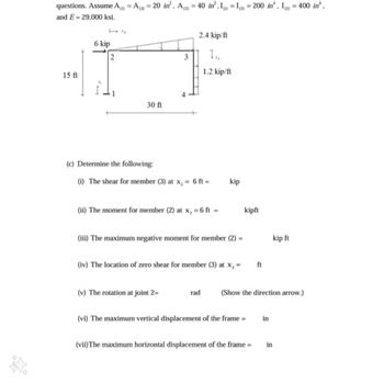
Assume A = A = 20 in², A = 40 in², I = I= 200 in. Ig = 400 in and E= 29,000 ksi.
Determine e following: (i) The shear for member (3) at x,= 6 ft = kip (ii) The moment for member (2) at x, = 6 ft = kipfu (iii) The maximum negative moment for member (2) = kip ft (iv) The location of zero shear for member (3) at x,= ft (v) The rotation at joint 2= rad (Show the direction arrow.) (vi) The maximum vertical displacement of the frame in (vii) The maximum horizontal displacement of the frame in

Transcribed Image Text:questions. Assume A() = A(3) = 20 in², A (2) = 40 in²,1) = I(3) = 200 in. I) = 400 in'.
and E 29,000 ksi.
6 kip
71
2.4 kip/ft
2
3
Tx,
1.2 kip/ft
15 ft
30 ft
(c) Determine the following:
(i) The shear for member (3) at x₁ = 6 ft =
kip
(ii) The moment for member (2) at x2 =
=6ft =
kipft
(iii) The maximum negative moment for member (2)
kip ft
(iv) The location of zero shear for member (3) at x₁ =
ft
(v) The rotation at joint 2=
rad
(Show the direction arrow.)
(vi) The maximum vertical displacement of the frame =
in
(vii) The maximum horizontal displacement of the frame =
in
Expert Solution
This question has been solved!
Explore an expertly crafted, step-by-step solution for a thorough understanding of key concepts.
Step by stepSolved in 2 steps

Knowledge Booster
Similar questions
- Calculate the forces in members AC, AD, and DE for the loaded truss. Restraining link BC is horizontal. Forces are positive if in tension, negative if in compression. B Answer: AC = 3' AD = i i DE = i C 3' 600 lb D 3' E lb lb lbarrow_forward*For the Howe bridge truss shown, d=11 ft,F1=3150 lb, F2=2150 lb, F3=2550 lb, and F4=4150 lb.* Pt A. Determine the forces in members CD, DH, and GH. Pt B. Determine the forces in members HI, BH, and BC.arrow_forwardDetermine the maximum shear stress and angle of twist (in degrees) of one tip with respect to other. The material of the component has a modulus of rigidity of 24 GPa. positive applied moments are CW when seen from E to A. Moment at A= 400 N.m Moment at B = -600 N.m Moment at C= 300 N.m Moment at D = 500 N.m Moment at E= -600 N.m L is 0.25m and Radius of the rod is 30mmarrow_forward
- Determine the force in member BC of the loaded truss. The force is positive if in tension, negative if in compression. 2.5 kips 3.9 kips 4.6 kips Answer: BC = i kipsarrow_forwardProblem 2: Determine the force in ALL the members of the truss. State if the members are in tension or compression. Show all your work to receive full credit. (Hint: It is not needed to find the reaction forces at C and E if you use the Method of Joints). Note: P1= 1000 lb and P: = 500 lb B C30 45 999 4 ft E 550 D. -4 ft- - 4 ft- 999 299arrow_forward
arrow_back_ios
arrow_forward_ios
Recommended textbooks for you

 Structural Analysis (10th Edition)Civil EngineeringISBN:9780134610672Author:Russell C. HibbelerPublisher:PEARSON
 Principles of Foundation Engineering (MindTap Cou...Civil EngineeringISBN:9781337705028Author:Braja M. Das, Nagaratnam SivakuganPublisher:Cengage Learning
 Fundamentals of Structural AnalysisCivil EngineeringISBN:9780073398006Author:Kenneth M. Leet Emeritus, Chia-Ming Uang, Joel LanningPublisher:McGraw-Hill Education
 Traffic and Highway EngineeringCivil EngineeringISBN:9781305156241Author:Garber, Nicholas J.Publisher:Cengage Learning


Structural Analysis (10th Edition)
Civil Engineering
ISBN:9780134610672
Author:Russell C. Hibbeler
Publisher:PEARSON

Principles of Foundation Engineering (MindTap Cou...
Civil Engineering
ISBN:9781337705028
Author:Braja M. Das, Nagaratnam Sivakugan
Publisher:Cengage Learning

Fundamentals of Structural Analysis
Civil Engineering
ISBN:9780073398006
Author:Kenneth M. Leet Emeritus, Chia-Ming Uang, Joel Lanning
Publisher:McGraw-Hill Education


Traffic and Highway Engineering
Civil Engineering
ISBN:9781305156241
Author:Garber, Nicholas J.
Publisher:Cengage Learning