
Structural Analysis
6th Edition
ISBN: 9781337630931
Author: KASSIMALI, Aslam.
Publisher: Cengage,
expand_more
expand_more
format_list_bulleted
Related questions
Question
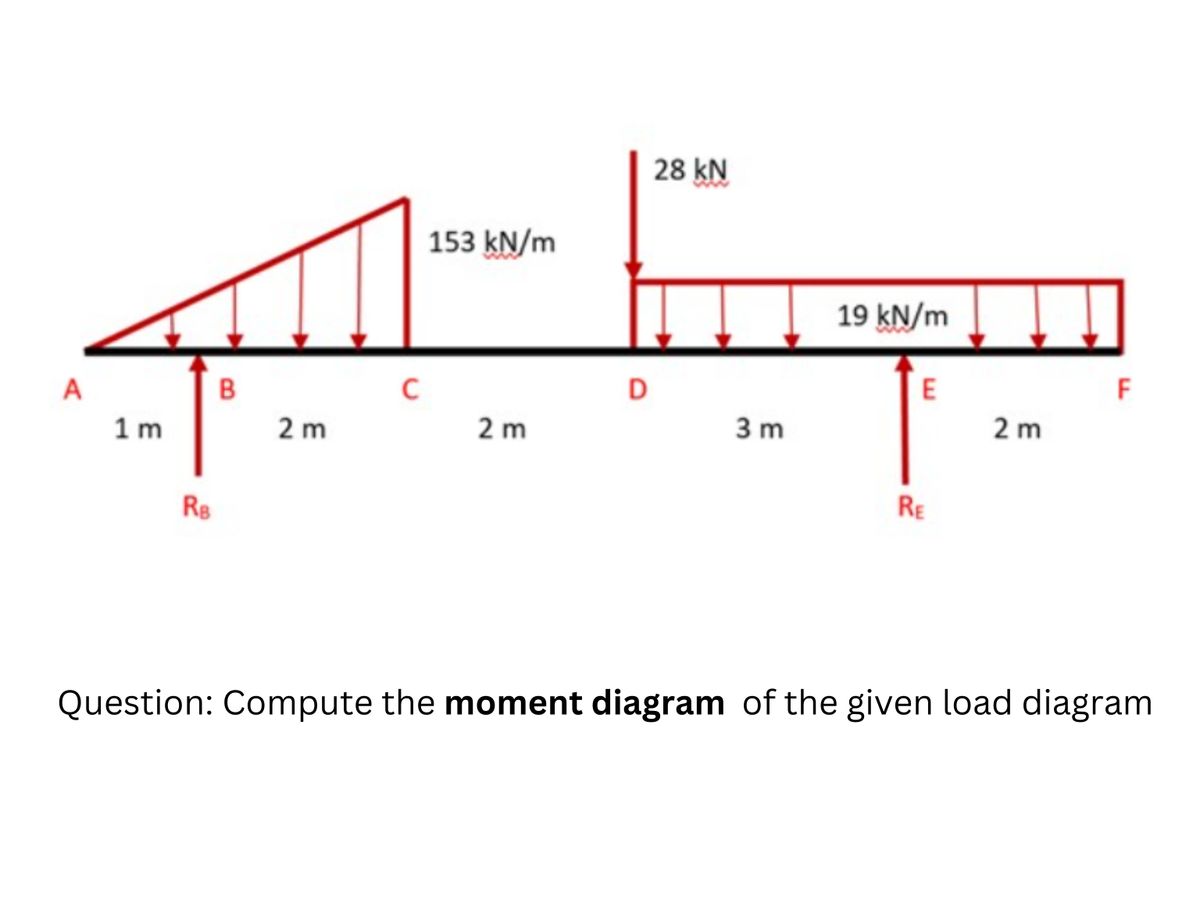

Transcribed Image Text:A
1m
RB
B
2m
C
153 kN/m
2 m
D
28 KN
3m
19 kN/m
E
RE
2 m
F
Question: Compute the moment diagram of the given load diagram
Expert Solution
This question has been solved!
Explore an expertly crafted, step-by-step solution for a thorough understanding of key concepts.

Step by stepSolved in 2 steps with 2 images

Knowledge Booster


Learn more about
Need a deep-dive on the concept behind this application? Look no further. Learn more about this topic, civil-engineering and related others by exploring similar questions and additional content below.Similar questions
- The beam carries various loadings as shown in the figure. An internal hinge is located at C. Calculate the maximum shearing force and maximum bending moment. What is the resultant reaction force and bending moment at support D? Draw the complete shear and moment diagrams on your solution paperarrow_forwardSolve the problem and answer the questions that follow. - If the supports were swapped such that the left support were a roller and the right support a pin, how would your solution change? - If the value of “w” were doubled, what would be the bending moment at the left most point of the beam?arrow_forwardQuestion 1 The steel framework of an office building is used to support lateral forces as shown in Figure Q1. If all the cross-sectional area are the same, draw (approximately) the bending moment diagram for girders STUVWX and column SMGA of that building by applying the cantilever method. 18 kN 30 kN 30 kN S M C 6 m T N H B ** 6 m U O 8m P Figure Q1: Building Frames 8 m W к 8 m X R T 4 m 4 m 4marrow_forward
- Solve the intermediate beam shown on the page using the slope deflection matter. Draw the deflected shape, free body diagrams, and the bending movement diagram for the structure with the maximas, minimas, zeros and their locationsarrow_forward1 ft 3 ft B 3 ft 3 ft (-9002 + 800f + 1000k) Ib.ft 6 ft 3 ft E (-300î – 400ĵ + 100k) Ibs The applied force at point E and the applied couple moment at point D are shown in the figure. Complete/calculate the following: (Where applicable, express the results as the (x, y, z) components of a Cartesian vector) 1. Draw the free-body diagram (FBD), showing the appropriate reaction forces and/or moments at the supports. (You must show the reactions in their component form i.e. show RAx, MRAX etc. on the FBD). Note: The support at point A is not able to resist a moment about the 'X' axis but is able to resist a force in this direction. 2. The unit vector ÅBc 3. The position vector Tɛ/a 4. The position vector īB/aarrow_forward
arrow_back_ios
arrow_forward_ios
Recommended textbooks for you
 Structural Analysis (10th Edition)Civil EngineeringISBN:9780134610672Author:Russell C. HibbelerPublisher:PEARSON
 Principles of Foundation Engineering (MindTap Cou...Civil EngineeringISBN:9781337705028Author:Braja M. Das, Nagaratnam SivakuganPublisher:Cengage Learning
 Fundamentals of Structural AnalysisCivil EngineeringISBN:9780073398006Author:Kenneth M. Leet Emeritus, Chia-Ming Uang, Joel LanningPublisher:McGraw-Hill Education
 Traffic and Highway EngineeringCivil EngineeringISBN:9781305156241Author:Garber, Nicholas J.Publisher:Cengage Learning
Structural Analysis (10th Edition)
Civil Engineering
ISBN:9780134610672
Author:Russell C. Hibbeler
Publisher:PEARSON
Principles of Foundation Engineering (MindTap Cou...
Civil Engineering
ISBN:9781337705028
Author:Braja M. Das, Nagaratnam Sivakugan
Publisher:Cengage Learning
Fundamentals of Structural Analysis
Civil Engineering
ISBN:9780073398006
Author:Kenneth M. Leet Emeritus, Chia-Ming Uang, Joel Lanning
Publisher:McGraw-Hill Education
Traffic and Highway Engineering
Civil Engineering
ISBN:9781305156241
Author:Garber, Nicholas J.
Publisher:Cengage Learning