Introductory Circuit Analysis (13th Edition)
13th Edition
ISBN: 9780133923605
Author: Robert L. Boylestad
Publisher: PEARSON
expand_more
expand_more
format_list_bulleted
Concept explainers
Question

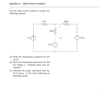
Transcribed Image Text:Question 4: Mesh-Current Analysis
Use the mesh current method to answer the
following quesions.
400
200.
2 A
0.5º,
10 V
(a) Write the simultaneous equations for the
circuit.
(b) Solve the simultaneous equations and find
the voltage vy. Explicitly show your cal-
culations.
(c) Calculate the power associated with the
10 V source. Is this source delivering or
absorbing power?
Expert Solution
This question has been solved!
Explore an expertly crafted, step-by-step solution for a thorough understanding of key concepts.
This is a popular solution
Trending nowThis is a popular solution!
Step by stepSolved in 3 steps with 4 images

Knowledge Booster
Learn more about
Need a deep-dive on the concept behind this application? Look no further. Learn more about this topic, electrical-engineering and related others by exploring similar questions and additional content below.Similar questions
- QUESTION 7 An 120 V AC circuit has 100 Q of resistance, 75 Q of inductive reactance (X ), and 25 Q of capacitive reactance (XC). Answer the following: A. The total impedance (Z) of this circuit is ohms. (Round your answer to one decimal place.) B. The total current flow in this circuit is -26.6 amps. (Round your answer to one decimal place.) C. The power factor in this circuit is 0.89 . (Round your answer to two decimal places.) degree lagging (leading or lagging) phase angle. (Round degrees to one decimal pla D. This circuit has a 26.6 Click Save and Submit to save and submit. Click Save All Answers to save all answers. Type here to search Pr F7 F6 DII F3 F5 F4 F2 &arrow_forwarda. For the circuit shown in Figure 4, calculate the Thevenin voltage, VTh, with respect to the terminals A and B, where RL is the load resistor. b. For the circuit shown in Figure 4, calculate the Thevenin resistance, RTh, with respect to the terminals A and B. c. For the circuit shown in Figure 4, what is the maximum amount of power that can be transferred to the load resistor RL?arrow_forwardThree resistors in parallel: RTotal = 1 R1 1 R2 1 R3 1) The circuit in figure (1) has, Vsupply =40 Volts, R₁ = 300 and R₂= 60 Q. RTotal = a) Calculte the total resistor for this parallel circuit. b) Calculata l₁ and 12, and verfy if |Total =l1 + 12 = c) Calculate the total current for this circuit. Total = Vsupply Figure (1) R₁ R2arrow_forward
arrow_back_ios
arrow_forward_ios
Recommended textbooks for you
 Introductory Circuit Analysis (13th Edition)Electrical EngineeringISBN:9780133923605Author:Robert L. BoylestadPublisher:PEARSON
 Delmar's Standard Textbook Of ElectricityElectrical EngineeringISBN:9781337900348Author:Stephen L. HermanPublisher:Cengage Learning
 Programmable Logic ControllersElectrical EngineeringISBN:9780073373843Author:Frank D. PetruzellaPublisher:McGraw-Hill Education
 Fundamentals of Electric CircuitsElectrical EngineeringISBN:9780078028229Author:Charles K Alexander, Matthew SadikuPublisher:McGraw-Hill Education
 Electric Circuits. (11th Edition)Electrical EngineeringISBN:9780134746968Author:James W. Nilsson, Susan RiedelPublisher:PEARSON
 Engineering ElectromagneticsElectrical EngineeringISBN:9780078028151Author:Hayt, William H. (william Hart), Jr, BUCK, John A.Publisher:Mcgraw-hill Education,

Introductory Circuit Analysis (13th Edition)
Electrical Engineering
ISBN:9780133923605
Author:Robert L. Boylestad
Publisher:PEARSON

Delmar's Standard Textbook Of Electricity
Electrical Engineering
ISBN:9781337900348
Author:Stephen L. Herman
Publisher:Cengage Learning

Programmable Logic Controllers
Electrical Engineering
ISBN:9780073373843
Author:Frank D. Petruzella
Publisher:McGraw-Hill Education

Fundamentals of Electric Circuits
Electrical Engineering
ISBN:9780078028229
Author:Charles K Alexander, Matthew Sadiku
Publisher:McGraw-Hill Education

Electric Circuits. (11th Edition)
Electrical Engineering
ISBN:9780134746968
Author:James W. Nilsson, Susan Riedel
Publisher:PEARSON

Engineering Electromagnetics
Electrical Engineering
ISBN:9780078028151
Author:Hayt, William H. (william Hart), Jr, BUCK, John A.
Publisher:Mcgraw-hill Education,