
Introductory Circuit Analysis (13th Edition)
13th Edition
ISBN: 9780133923605
Author: Robert L. Boylestad
Publisher: PEARSON
expand_more
expand_more
format_list_bulleted
Related questions
Concept explainers
Question
2.3
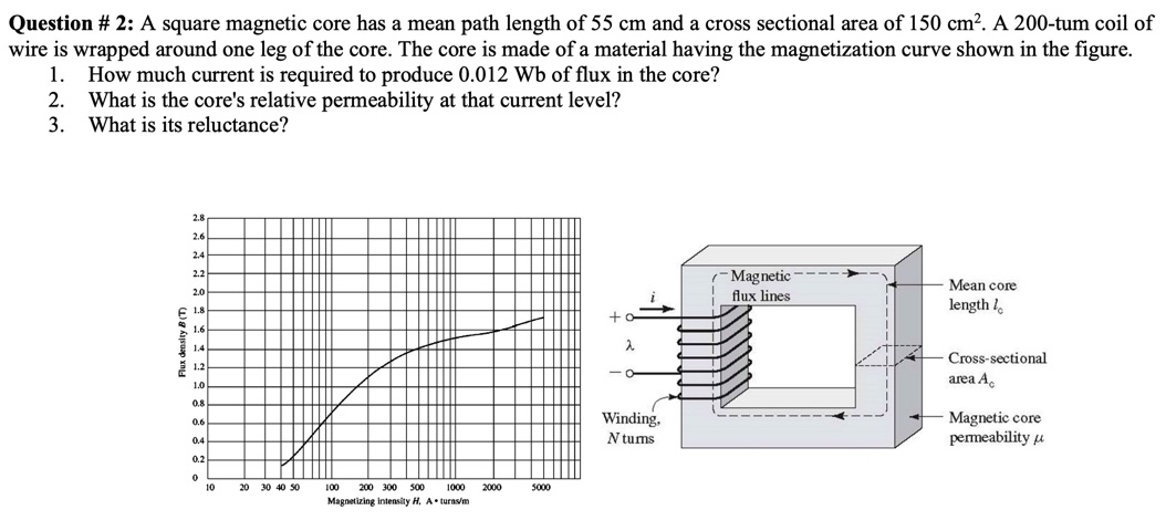

Transcribed Image Text:Question # 2: A square magnetic core has a mean path length of 55 cm and a cross sectional area of 150 cm?. A 200-tum coil of
wire is wrapped around one leg of the core. The core is made of a material having the magnetization curve shown in the figure.
1.
How much current is required to produce 0.012 Wb of flux in the core?
What is the core's relative permeability at that current level?
3. What is its reluctance?
2.
2.8
2.6
2.4
- Magnetic
2.2
----
2.0
E 1.8
Mean core
length l.
flux lines
1.6
1.4
Cross-sectional
1.2
area A.
1.0
0.8
Winding.
Magnetic core
permeability u
0.6
0.4
N tums
0.2
10
20 30 40 50
100
200 300 50
1000
2000
5000
Magnetizing intensity H, A turnsm
Expert Solution
This question has been solved!
Explore an expertly crafted, step-by-step solution for a thorough understanding of key concepts.

Step by stepSolved in 3 steps with 3 images

Knowledge Booster


Learn more about
Need a deep-dive on the concept behind this application? Look no further. Learn more about this topic, electrical-engineering and related others by exploring similar questions and additional content below.Similar questions
- QV Find the equivalent Resistance between (asb) for below question. 300 120 512 ww 2011 ww 25 S2 600 100arrow_forwardD2 Red B1 LDR1 PSB (+ R4 5 V 5.1 kQ Q1 2N2222 R3 5.1 kQarrow_forwardDetermine the voltage through the 10 kilo-ohm resistor at terminals a-b. a. 0.21645 b. 6.9264 c. 1.2324 d. 2.3810 e. None of the abovearrow_forward
- Answer the following questions: regarding LEDarrow_forwardPiz Area 2 Area 1 Xlic 11.In the figure shown above, if the power transferred from area 1 to area 2 is increased by AP12-0.037037 pu due to load 2 increase by APL2 0.010 pu, B1 0.20, D2-0.02, then the value of R2 is: a. 3 b. 3.5 c. 4 d. 5 e. nonearrow_forward(Q2.2) Find the current through the resistor R1 in the direction from left to right. (Unit: A) (Q2.3) Find the current through the resistor R2 in the direction from left to right. (Unit: A) (Q2.4) Find the current through the resistor R3 in the direction from left to right. (Unit: A) (Q2.5) Find the potential of the node "a" with respect to the ground node indicated in the circuit diagram. (Unit: V) (Q2.6) Find the potential of the node "b" with respect to the ground node indicated in the circuit diagram. (Unit: V) (Q2.7) Find the potential of the node "c" with respect to the ground node indicated in the circuit diagram. (Unit: V)arrow_forward
- Given the circuit below with 10 = 20 A, R1 = 4 ohms, R2 = 6 ohms, R2 ww 10 R1 Question 9: Find the Norton equivalent current. Be sure to select your answer in the quiz and sho a. 8 A b. 10 A c. 12 A d. 6 A e. Write in your answerarrow_forwardFor the element in the Figure below., v1 = 17 V. Determine v2.arrow_forwardDetermine the voltage drop across each element, the current through each element, the resistance of each element, the power consumed by each element, the total resistance, source current, and total power. Additionally, determine R2 & Vs.arrow_forward
arrow_back_ios
arrow_forward_ios
Recommended textbooks for you
- Introductory Circuit Analysis (13th Edition)Electrical EngineeringISBN:9780133923605Author:Robert L. BoylestadPublisher:PEARSON
 Delmar's Standard Textbook Of ElectricityElectrical EngineeringISBN:9781337900348Author:Stephen L. HermanPublisher:Cengage Learning
 Programmable Logic ControllersElectrical EngineeringISBN:9780073373843Author:Frank D. PetruzellaPublisher:McGraw-Hill Education
  Fundamentals of Electric CircuitsElectrical EngineeringISBN:9780078028229Author:Charles K Alexander, Matthew SadikuPublisher:McGraw-Hill Education
 Electric Circuits. (11th Edition)Electrical EngineeringISBN:9780134746968Author:James W. Nilsson, Susan RiedelPublisher:PEARSON
 Engineering ElectromagneticsElectrical EngineeringISBN:9780078028151Author:Hayt, William H. (william Hart), Jr, BUCK, John A.Publisher:Mcgraw-hill Education,
Introductory Circuit Analysis (13th Edition)
Electrical Engineering
ISBN:9780133923605
Author:Robert L. Boylestad
Publisher:PEARSON
Delmar's Standard Textbook Of Electricity
Electrical Engineering
ISBN:9781337900348
Author:Stephen L. Herman
Publisher:Cengage Learning
Programmable Logic Controllers
Electrical Engineering
ISBN:9780073373843
Author:Frank D. Petruzella
Publisher:McGraw-Hill Education
Fundamentals of Electric Circuits
Electrical Engineering
ISBN:9780078028229
Author:Charles K Alexander, Matthew Sadiku
Publisher:McGraw-Hill Education
Electric Circuits. (11th Edition)
Electrical Engineering
ISBN:9780134746968
Author:James W. Nilsson, Susan Riedel
Publisher:PEARSON
Engineering Electromagnetics
Electrical Engineering
ISBN:9780078028151
Author:Hayt, William H. (william Hart), Jr, BUCK, John A.
Publisher:Mcgraw-hill Education,