Introductory Circuit Analysis (13th Edition)
13th Edition
ISBN: 9780133923605
Author: Robert L. Boylestad
Publisher: PEARSON
expand_more
expand_more
format_list_bulleted
Concept explainers
Question
thumb_up100%
Tools and Materials for Use
1.Power supply(EMS 8821, 0-120[V])
2. transformer(EMS 8341)
3. single phase power meter(EMS 8431, 750[W])
4. alternating current meter (EMS 8425, 0.5/0.5/0.5 [A])
5. alternating volt meter (EMS 8426, 250[V])
6. connection leads (EMS 8941)
question,
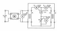
1. Is the load current IL [A] equal to the sum of current I1,I2 flowing to each transformer? If not for what reason?

Transcribed Image Text:I,
0-0.5
Aac
0-0.5
Aac
A
A
I.
A
0-2.5(A)
Aac
0-250
Vac
V
30
0-120
Vac
W.
10-250
Vac
EL
RL
V
Expert Solution
This question has been solved!
Explore an expertly crafted, step-by-step solution for a thorough understanding of key concepts.
Step by stepSolved in 2 steps

Knowledge Booster
Learn more about
Need a deep-dive on the concept behind this application? Look no further. Learn more about this topic, electrical-engineering and related others by exploring similar questions and additional content below.Similar questions
- A 4-bus three-phase power system consists of the following equipment: • Generator 1 connected to bus 1 with a rated power of 20MVA, rated voltage of 20 kV, and a series reactance of 0.4 p.u. • Generator 2 connected to bus 5, with a rated power of 12MVA, rated voltage of 10 kV, and a series reactance of 0.3 p.u. Transformer 1 connected between buses 1 and 2, is wye-wye connected with a rated power of 20 MVA, rated voltages 20/100 kV, and a series reactance of 0.1 p.u. • Transformer 2 connected between buses 4 and 5, is wye-wye connected with a rated power of 12 MVA, rated voltages 12/110 kV, and a series reactance of 0.15 p.u. • Transmission Line 2-3 connects buses 2 and 3 and had a series impedance of 50 + j75 ohms. • Transmission Line 3-4 connects buses 3 and 4 and had a series impedance of 40 + j80 ohms. • Load A connected to bus 3 and abosorbes20 MW and 10 MVAR. The voltage at bus 3 is 105 kV. 1) Draw the one-line diagram for the system. 2) Draw the per-unit, per phase…arrow_forward"Electrical machines/ I need a complete and clear solution for all sub -questions of a single question. Thank you."arrow_forwardThis is a practice question from my Introduction to Circuits course. I'm not sure how to even start this. Thank you for your assistance.arrow_forward
arrow_back_ios
arrow_forward_ios
Recommended textbooks for you
 Introductory Circuit Analysis (13th Edition)Electrical EngineeringISBN:9780133923605Author:Robert L. BoylestadPublisher:PEARSON
 Delmar's Standard Textbook Of ElectricityElectrical EngineeringISBN:9781337900348Author:Stephen L. HermanPublisher:Cengage Learning
 Programmable Logic ControllersElectrical EngineeringISBN:9780073373843Author:Frank D. PetruzellaPublisher:McGraw-Hill Education
 Fundamentals of Electric CircuitsElectrical EngineeringISBN:9780078028229Author:Charles K Alexander, Matthew SadikuPublisher:McGraw-Hill Education
 Electric Circuits. (11th Edition)Electrical EngineeringISBN:9780134746968Author:James W. Nilsson, Susan RiedelPublisher:PEARSON
 Engineering ElectromagneticsElectrical EngineeringISBN:9780078028151Author:Hayt, William H. (william Hart), Jr, BUCK, John A.Publisher:Mcgraw-hill Education,

Introductory Circuit Analysis (13th Edition)
Electrical Engineering
ISBN:9780133923605
Author:Robert L. Boylestad
Publisher:PEARSON

Delmar's Standard Textbook Of Electricity
Electrical Engineering
ISBN:9781337900348
Author:Stephen L. Herman
Publisher:Cengage Learning

Programmable Logic Controllers
Electrical Engineering
ISBN:9780073373843
Author:Frank D. Petruzella
Publisher:McGraw-Hill Education

Fundamentals of Electric Circuits
Electrical Engineering
ISBN:9780078028229
Author:Charles K Alexander, Matthew Sadiku
Publisher:McGraw-Hill Education

Electric Circuits. (11th Edition)
Electrical Engineering
ISBN:9780134746968
Author:James W. Nilsson, Susan Riedel
Publisher:PEARSON

Engineering Electromagnetics
Electrical Engineering
ISBN:9780078028151
Author:Hayt, William H. (william Hart), Jr, BUCK, John A.
Publisher:Mcgraw-hill Education,