
Power System Analysis and Design (MindTap Course List)
6th Edition
ISBN: 9781305632134
Author: J. Duncan Glover, Thomas Overbye, Mulukutla S. Sarma
Publisher: Cengage Learning
expand_more
expand_more
format_list_bulleted
Related questions
Question
thumb_up100%
Electric Machines/ I need the expert solution handwritten with the mention of the law or diagram for a clear solution.

Transcribed Image Text:Question 1
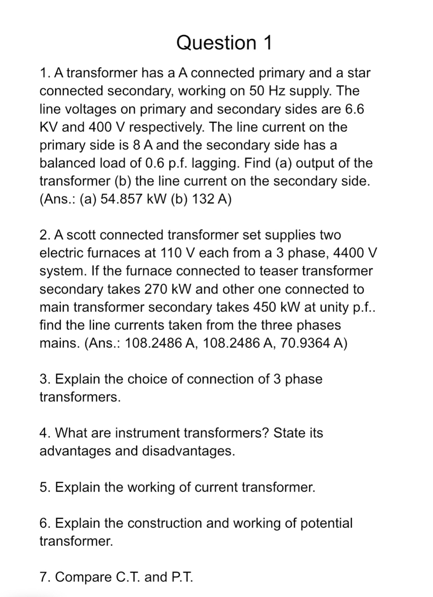
1. A transformer has a A connected primary and a star
connected secondary, working on 50 Hz supply. The
line voltages on primary and secondary sides are 6.6
KV and 400 V respectively. The line current on the
primary side is 8 A and the secondary side has a
balanced load of 0.6 p.f. lagging. Find (a) output of the
transformer (b) the line current on the secondary side.
(Ans. (a) 54.857 kW (b) 132 A)
2. A scott connected transformer set supplies two
electric furnaces at 110 V each from a 3 phase, 4400 V
system. If the furnace connected to teaser transformer
secondary takes 270 kW and other one connected to
main transformer secondary takes 450 kW at unity p.f..
find the line currents taken from the three phases
mains. (Ans.: 108.2486 A, 108.2486 A, 70.9364 A)
3. Explain the choice of connection of 3 phase
transformers.
4. What are instrument transformers? State its
advantages and disadvantages.
5. Explain the working of current transformer.
6. Explain the construction and working of potential
transformer.
7. Compare C.T. and P.T.
Expert Solution
This question has been solved!
Explore an expertly crafted, step-by-step solution for a thorough understanding of key concepts.

Step by stepSolved in 2 steps

Knowledge Booster

Similar questions
- For a short-circuit test on a 2-winding transformer, with one winding shorted, can you apply the rated voltage on the other winding? (a) Yes (b) Noarrow_forwardFor an ideal 2-winding transformer, an impedance Z2 connected across winding 2 (secondary) is referred to winding 1 (primary) by multiplying Z2 by (a) The turns ratio (N1/N2) (b) The square of the turns ratio (N1/N2)2 (c) The cubed turns ratio (N1/N2)3arrow_forwardFor an ideal transformer, the efficiency is (a) 0 (b) 100 (c) 50arrow_forward
- A single-phase, 50-kVA,2400/240-V,60-Hz distribution transformer has the following parameters: Resistance of the 2400-V winding: R1=0.75 Resistance of the 240-V winding: R2=0.0075 Leakage reactance of the 2400-V winding: X1=1.0 Leakage reactance of the 240-V winding: X2=0.01 Exciting admittance on the 240-V side =0.003j0.02S (a) Draw the equivalent circuit referred to the high-voltage side of the transformer. (b) Draw the equivalent circuit referred to the low-voltage side of the transformer. Show the numerical values of impedances on the equivalent circuits.arrow_forwardA single-phase step-down transformer is rated 13MVA,66kV/11.5kV. With the 11.5 kV winding short-circuited, rated current flows when the voltage applied to the primary is 5.5 kV. The power input is read as 100 kW. Determine Req1andXeq1 in ohms referred to the high-voltage winding.arrow_forwardA 23/230-kV step-up transformer feeds a three-phase transmission line, which in turn supplies a 150-MVA,0.8 lagging power factor load through a step-down 230/23-kV transformer. The impedance of the line and transformers at 230kVis18+j60. Determine the tap setting for each transformer to maintain the voltage at the load at 23 kV.arrow_forward
- Consider an ideal transformer with N1=3000andN2=1000 turns. Let winding 1 be connected to a source whose voltage is e1(t)=100(1| t |)volts for 1t1ande1(t)=0 for | t |1 second. A2- farad capacitor is connected across winding 2. Sketch e1(t),e2(t),i1(t),andi2(t) versus time t.arrow_forwardAn ideal transformer has no real or reactive power loss. (a) True (b) Falsearrow_forwardThe ratings of a three-phase three-winding transformer are Primary(1): Y connected 66kV,15MVA Secondary (2): Y connected, 13.2kV,10MVA Tertiary (3): A connected, 2.3kV,5MVA Neglecting winding resistances and exciting current, the per-unit leakage reactances are X12=0.08 on a 15-MVA,66-kV base X13=0.10 on a 15-MVA,66-kV base X23=0.09 on a 10-MVA,13.2-kV base (a) Determine the per-unit reactances X1,X2,X3 of the equivalent circuit on a 15-MVA,66-kV base at the primary terminals. (b) Purely resistive loads of 7.5 MW at 13.2 kV and 5 MW at 2.3kV are connected to the secondary and tertiary sides of the transformer, respectively. Draw the per- unit impedance diagram, showing the per-unit impedances on a 15-MVA,66-kV base at the primary terminals.arrow_forward
- (a) An ideal single-phase two-winding transformer with turns ratio at=N1/N2 is connected with a series impedance Z2 across winding 2. If one wants to replace Z2, with a series impedance Z1 across winding 1 and keep the terminal behavior of the two circuits to be identical, find Z1 in terms of Z2. (b) Would the above result be true if instead of a series impedance there is a shunt impedance? (c) Can one refer a ladder network on the secondary (2) side to the primary (1) side simply by multiplying every impedance byat2 ?arrow_forwardThe symbol shown is a(n) a. iron core transformer. b. auto transformer. c. current transformer. d. air core transformer.arrow_forwardConsider the three single-phase two-winding transformers shown in Figure 3.37. The high-voltage windings are connected in Y. (a) For the low-voltage side, connect the windings in , place the polarity marks, and label the terminals a, b, and c in accordance with the American standard. (b) Relabel the terminals a, b, and c such that VAN is 90 out of phase with Va for positive sequence.arrow_forward
arrow_back_ios
SEE MORE QUESTIONS
arrow_forward_ios
Recommended textbooks for you
- Power System Analysis and Design (MindTap Course ...Electrical EngineeringISBN:9781305632134Author:J. Duncan Glover, Thomas Overbye, Mulukutla S. SarmaPublisher:Cengage Learning

 Electricity for Refrigeration, Heating, and Air C...Mechanical EngineeringISBN:9781337399128Author:Russell E. SmithPublisher:Cengage Learning
Power System Analysis and Design (MindTap Course ...
Electrical Engineering
ISBN:9781305632134
Author:J. Duncan Glover, Thomas Overbye, Mulukutla S. Sarma
Publisher:Cengage Learning
Electricity for Refrigeration, Heating, and Air C...
Mechanical Engineering
ISBN:9781337399128
Author:Russell E. Smith
Publisher:Cengage Learning