
Introductory Circuit Analysis (13th Edition)
13th Edition
ISBN: 9780133923605
Author: Robert L. Boylestad
Publisher: PEARSON
expand_more
expand_more
format_list_bulleted
Related questions
Concept explainers
Question
Do b),c),d),e),f),g),h)?
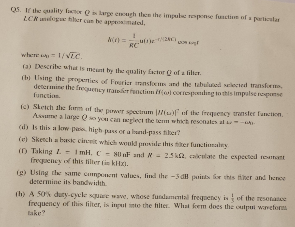

Transcribed Image Text:Q5. If the quality factor Q is large enough then the impulse response function of a particular
LCR analogue filter can be approximated,
h(1) =
()e-1/(2RC)
RC
cos wot
%3D
where wo = 1/VLC.
%3D
(a) Describe what is meant by the quality factor Q of a filter.
(b) Using the properties of Fourier transforms and the tabulated selected transforms,
determine the frequency transfer function H(w) corresponding to this impulse response
function.
(c) Sketch ihe form of the power spectrum |H(w)|² of the frequency transfer function.
Assume a large Q so you can neglect the term which resonates at w = -wo-
(d) Is this a low-pass, high-pass
or a band-pass filter?
(e) Sketch a basic circuit which would provide this filter functionality.
(f) Taking L
frequency of this filter (in kHz).
1 mH, C = 80 nF and R
2.5 k2, calculate the expected resonant
%3D
%3D
(g) Using the same component values, find the -3 dB points for this filter and hence
determine its bandwidth.
(h) A 50% duty-cycle square wave, whose fundamental frequency is of the resonance
frequency of this filter, is input into the filter. What form does the output waveform
take?
Expert Solution
This question has been solved!
Explore an expertly crafted, step-by-step solution for a thorough understanding of key concepts.

This is a popular solution

Trending nowThis is a popular solution!

Step by stepSolved in 2 steps with 2 images

Knowledge Booster


Learn more about
Need a deep-dive on the concept behind this application? Look no further. Learn more about this topic, electrical-engineering and related others by exploring similar questions and additional content below.Similar questions
- e6arrow_forwardQ6 AM signal [A+mc+)]. Coscwet for Sketch the the gien periodic trienyle cigral met) – maryle cigral met) met) 10 - - 10-3 と -10.. i) Sketeh r p=0.5 i) Pind anyptitude & 1 and fr pzos. & efficieney Jor ii) find fat side band. pooer8 efficiency gor paor g camier the case (i).arrow_forwardBriefly describe the differences between Fourier Transforms and Discrete Fourier Transforms.arrow_forward
- A dc-dc converter is built so that Vout(t) = q1Vin(t). The switch operates at 50 kHz withduty ratio of 50 %. This output voltage is applied to the input of a simple one-polelow-pass filter with a corner frequency at 500 Hz. What is the Fourier series of thesignal at the filter output?arrow_forwardSIGNALS AND INFORMNATIONSarrow_forwardQ1/ Explain: 1- phase and spectrum plot. 2- Duality of fourier transform. 3- Bandwidth. 4- What is the convolution in time domain and What convolution becomes in frequency domain .arrow_forward
- Determine the fundamental frequency ?0 and the fundamental period ?0 for the two continuous-time multi-tone periodic signals.a. ?1(?) = cos(2.4??) + cos(4??)b. ?2(?) = sin(4.9??) + cos(7??)arrow_forwardThe signal x(t) = sinc(21) is sampled at 4 Hz to obtain the sampled signal, x, (1). - (a) Derive the Fourier transform, X, (f), of the sampled signal x, (t) and sketch its S spectrum. (b) What is the Nyquist sampling frequency? (c) If x(t) is sampled at a frequency of 2 Hz, sketch and label the sampled signal.arrow_forwardAn FM radio broadcast used a modulator with a frequency deviation sensitivity of 5KHz/V, a 2Vp – 10 kHz modulating signal, and a 10Vp – 88MHz carrier Signal , determine. Use this Bessel table below to solve this problem. (a) Actual minimum bandwidth from the Bessel function table in kHzarrow_forward
- For the amplitude modulated signal spectrum shown below, find the following: a) Write an expression for the waveform in terms of ωm and ωc. b) Name the modulation technique.arrow_forward3arrow_forwardThe input signal shown in the following figure was input to a system with a Fourier the magnitude transform value as described in the reference column below. Draw spectrum of the output signal. (Exactly) Note: Fourier transform values of the system impulse function: II (- -) 20 The input signal is as follows. -To 0 To To 0.5sec T-1/7sec, A=7/2arrow_forward
arrow_back_ios
SEE MORE QUESTIONS
arrow_forward_ios
Recommended textbooks for you
- Introductory Circuit Analysis (13th Edition)Electrical EngineeringISBN:9780133923605Author:Robert L. BoylestadPublisher:PEARSON
 Delmar's Standard Textbook Of ElectricityElectrical EngineeringISBN:9781337900348Author:Stephen L. HermanPublisher:Cengage Learning
 Programmable Logic ControllersElectrical EngineeringISBN:9780073373843Author:Frank D. PetruzellaPublisher:McGraw-Hill Education
  Fundamentals of Electric CircuitsElectrical EngineeringISBN:9780078028229Author:Charles K Alexander, Matthew SadikuPublisher:McGraw-Hill Education
 Electric Circuits. (11th Edition)Electrical EngineeringISBN:9780134746968Author:James W. Nilsson, Susan RiedelPublisher:PEARSON
 Engineering ElectromagneticsElectrical EngineeringISBN:9780078028151Author:Hayt, William H. (william Hart), Jr, BUCK, John A.Publisher:Mcgraw-hill Education,
Introductory Circuit Analysis (13th Edition)
Electrical Engineering
ISBN:9780133923605
Author:Robert L. Boylestad
Publisher:PEARSON
Delmar's Standard Textbook Of Electricity
Electrical Engineering
ISBN:9781337900348
Author:Stephen L. Herman
Publisher:Cengage Learning
Programmable Logic Controllers
Electrical Engineering
ISBN:9780073373843
Author:Frank D. Petruzella
Publisher:McGraw-Hill Education
Fundamentals of Electric Circuits
Electrical Engineering
ISBN:9780078028229
Author:Charles K Alexander, Matthew Sadiku
Publisher:McGraw-Hill Education
Electric Circuits. (11th Edition)
Electrical Engineering
ISBN:9780134746968
Author:James W. Nilsson, Susan Riedel
Publisher:PEARSON
Engineering Electromagnetics
Electrical Engineering
ISBN:9780078028151
Author:Hayt, William H. (william Hart), Jr, BUCK, John A.
Publisher:Mcgraw-hill Education,