
Elements Of Electromagnetics
7th Edition
ISBN: 9780190698614
Author: Sadiku, Matthew N. O.
Publisher: Oxford University Press
expand_more
expand_more
format_list_bulleted
Related questions
Concept explainers
Question
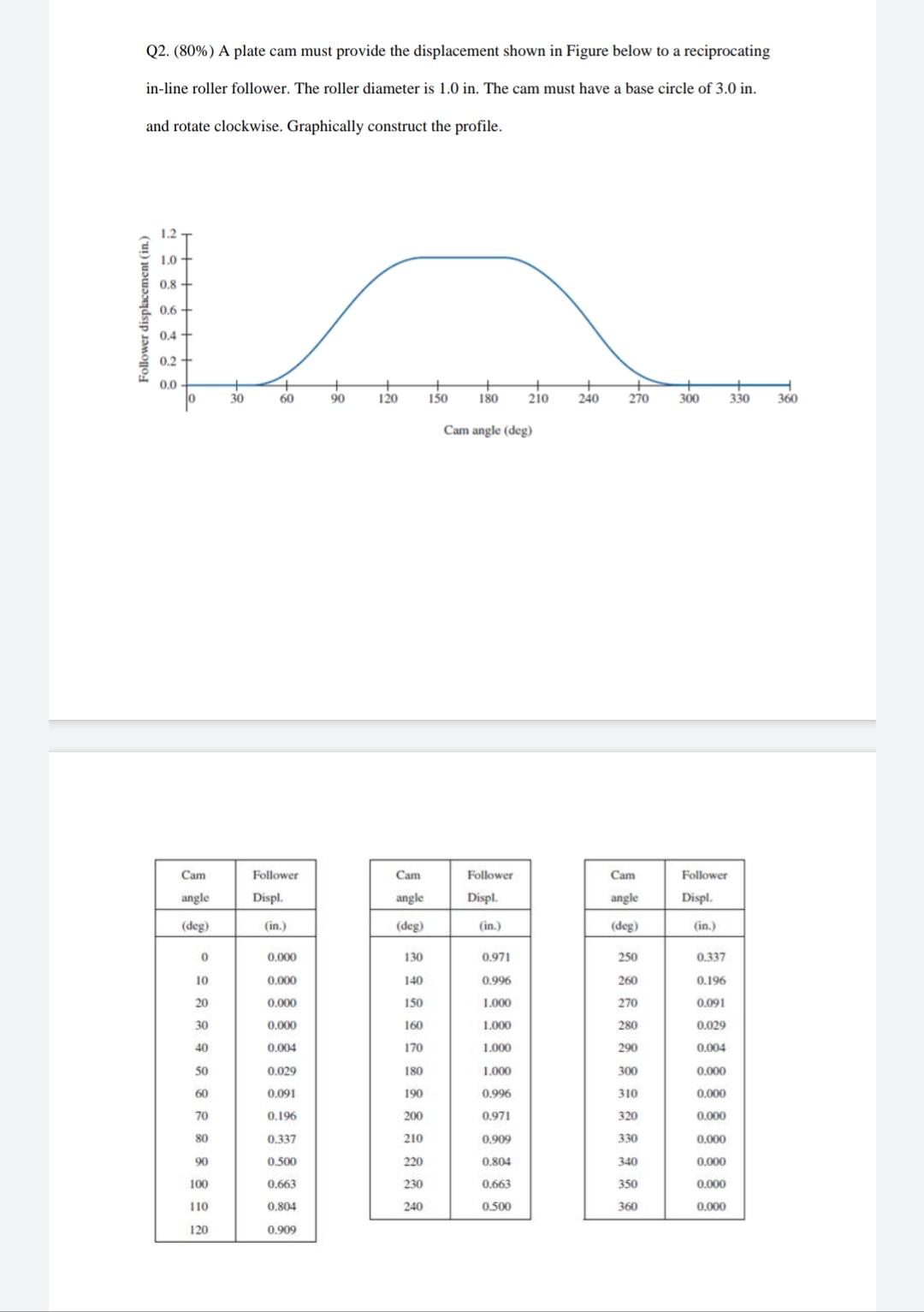

Transcribed Image Text:Q2. (80%) A plate cam must provide the displacement shown in Figure below to a reciprocating
in-line roller follower. The roller diameter is 1.0 in. The cam must have a base circle of 3.0 in.
and rotate clockwise. Graphically construct the profile.
1.2
1.0
0.8
0.6 -
0,4 -
0.2 +
0.0 -
30
60
90
120
150
180
210
240
270
300
330
360
Cam angle (deg)
Cam
Follower
Cam
Follower
Cam
Follower
angle
Displ.
angle
Displ.
angle
Displ.
(deg)
(in.)
(deg)
(in.)
(deg)
(in.)
0,000
130
0.971
250
0.337
10
0.000
140
0.996
260
0.196
20
0.000
150
1.000
270
0.091
30
0.000
160
1.000
280
0.029
40
0.004
170
1.000
290
0.004
50
0.029
180
1.000
300
0.000
60
0.091
190
0.996
310
0.000
70
0.196
200
0.971
320
0.000
80
0.337
210
0.909
330
0.000
90
0.500
220
0.804
340
0.000
100
0.663
230
0.663
350
0,000
10
0,804
240
0.500
360
0.000
120
0.909
Expert Solution
This question has been solved!
Explore an expertly crafted, step-by-step solution for a thorough understanding of key concepts.

This is a popular solution

Trending nowThis is a popular solution!

Step by stepSolved in 3 steps with 4 images

Knowledge Booster


Learn more about
Need a deep-dive on the concept behind this application? Look no further. Learn more about this topic, mechanical-engineering and related others by exploring similar questions and additional content below.Similar questions
- Design a cam profile with an inline knife edge follower that has dwell during the first second, rise of 5cm with cycloidal motion for another 2 seconds before dwell for half second, then return with simple harmonic motion for the rest of time to complete one revolution. The cam rotates with a constant speed of 15rpm CCW. The nearest approach of the follower to the cam is 3cm.arrow_forwardDraw the cam profile for a knife-edge follower having the followingmotion: rise 50 mm during 150 deg turn with gravitational motion, dwell for 30deg, fall 50 mm during 150 deg turn with gravitational motion, and dwell for 30deg. Use 100 mm base circle. Cam rotates clockwise. Scale 1:1arrow_forwardA 10 pitch pinion with 20 teeth mates with a gear having 80 teeth The pinion rotates at 3,000 RPM. The gear pair is to be installed in a rectangular housing where a minimum of 0.20 in clearance botween the gears and housing is requirod. Specify the dimensions X and Y as shown in tho figure below Note: This question requires a file attachinent, which can be pdf, ipeg. word, excol or power point. Show all your calculations. Handwritten calculations are acceptable. 0.20 in 0.20 In 0.20 in GEAR PINION N, 20arrow_forward
- Draw the displacement diagram and profile of the cam operating a roller reciprocating follower and with the following data: Shaft diameter 10 mm; Minimum radius of cam 25mm; lift = 40mm; roller diameter=15mm. The cam lifts the follower for 120° with Simple Harmonic Motion (SHM) followed by a Dwell of 30° .Then follower lowers down during 150° of cam rotation with SHM followed by a Dwell period. If the cam rotates at a uniform speed of 100 RPM clockwise direction. Calculate the maximum velocity and acceleration during the ascent and descent period. Maximum Velocity and Acceleration During Ascent and Descentarrow_forward3. 100-gram oil at 20°C and 50-gram iron at 75 °C are placed in 200-gram iron container. The increase in temperature of the container is 5°C and the specific heat of oil is 0.43 cal/g °C. What is the specific heat of the iron?arrow_forwardan airplane turbofan compressor blade is 3.0 m long and is rotating at 12350 rmp. Calculate the following- angular speed, w_____________rad/s linear spped at the tip of the blade, v=_________m/s angular and linear displacement after 3.3s, 0= ___________rad s______________marrow_forward
- The maximum sliding velocity of the teeth of two gear wheels in mesh is 0.32 m/s. The wheels are of module 5 mm and have 32 and 44 teeth respectively. The addendum for each wheel is 1.2 times the module and the pressure angle is 20°. Calculate: 2.1. The number of teeth in contact. 2.2. The angular speed of each wheel.arrow_forwardDoarrow_forward
arrow_back_ios
arrow_forward_ios
Recommended textbooks for you
- Elements Of ElectromagneticsMechanical EngineeringISBN:9780190698614Author:Sadiku, Matthew N. O.Publisher:Oxford University Press
 Mechanics of Materials (10th Edition)Mechanical EngineeringISBN:9780134319650Author:Russell C. HibbelerPublisher:PEARSON
 Thermodynamics: An Engineering ApproachMechanical EngineeringISBN:9781259822674Author:Yunus A. Cengel Dr., Michael A. BolesPublisher:McGraw-Hill Education
  Control Systems EngineeringMechanical EngineeringISBN:9781118170519Author:Norman S. NisePublisher:WILEY
 Mechanics of Materials (MindTap Course List)Mechanical EngineeringISBN:9781337093347Author:Barry J. Goodno, James M. GerePublisher:Cengage Learning
 Engineering Mechanics: StaticsMechanical EngineeringISBN:9781118807330Author:James L. Meriam, L. G. Kraige, J. N. BoltonPublisher:WILEY
Elements Of Electromagnetics
Mechanical Engineering
ISBN:9780190698614
Author:Sadiku, Matthew N. O.
Publisher:Oxford University Press
Mechanics of Materials (10th Edition)
Mechanical Engineering
ISBN:9780134319650
Author:Russell C. Hibbeler
Publisher:PEARSON
Thermodynamics: An Engineering Approach
Mechanical Engineering
ISBN:9781259822674
Author:Yunus A. Cengel Dr., Michael A. Boles
Publisher:McGraw-Hill Education
Control Systems Engineering
Mechanical Engineering
ISBN:9781118170519
Author:Norman S. Nise
Publisher:WILEY
Mechanics of Materials (MindTap Course List)
Mechanical Engineering
ISBN:9781337093347
Author:Barry J. Goodno, James M. Gere
Publisher:Cengage Learning
Engineering Mechanics: Statics
Mechanical Engineering
ISBN:9781118807330
Author:James L. Meriam, L. G. Kraige, J. N. Bolton
Publisher:WILEY