
Introductory Circuit Analysis (13th Edition)
13th Edition
ISBN: 9780133923605
Author: Robert L. Boylestad
Publisher: PEARSON
expand_more
expand_more
format_list_bulleted
Related questions
Concept explainers
Question
Do b, c and d?

Transcribed Image Text:Find the time-domain response to a unit impulse input for a system described
by the transfer function
Q1
(a)
s+1
G(s)
s2 + 2s + 13
(b)
A system has the closed-loop transfer function
G(s)
(s + 3)(s² – 4s + 13)
Sketch the Pole-Zero plot for this system. Comment on the stability and
response characteristics of the system.
A PD controller with proportional gain Kp and derivative gain Ka is in series
with a plant with the transfer function
(c)
4
G(s)
%3D
s+ 0.5
and employs a unity negative feedback loop. Find suitable values for K, and Ka
so that the closed-loop system has a time constant t = 4 sec, and the closed-
loop response to a step input is 0.98.
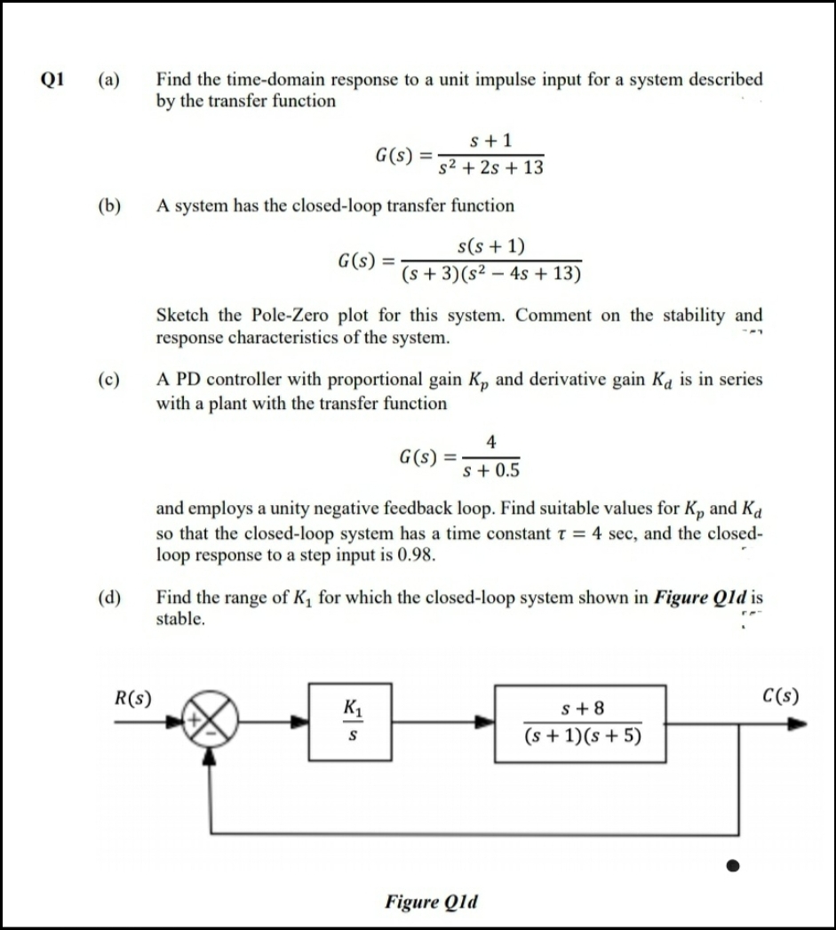
(d)
Find the range of K, for which the closed-loop system shown in Figure Qld is
stable.
R(s)
C(s)
K1
s+ 8
(s + 1)(s+ 5)
S
Figure Qld
Expert Solution
This question has been solved!
Explore an expertly crafted, step-by-step solution for a thorough understanding of key concepts.

Step by stepSolved in 2 steps with 2 images

Knowledge Booster


Learn more about
Need a deep-dive on the concept behind this application? Look no further. Learn more about this topic, electrical-engineering and related others by exploring similar questions and additional content below.Similar questions
- Below shows the circuit diagram of a remote control. Explain the operating concept of this simple circuit diagram and how it works to produce the signal.arrow_forwardWhat is the purpose of multiplier resistors in a voltmeter? A. To extend the range of the voltmeter. B. To shunt current around the meter movement. C. To shunt voltage around the meter movement. D. To limit voltage at the input of the voltmeter.arrow_forwardThe circuit is in continuity mode before the switch is opened. Select one: O a. 2. Select the option that corresponds to the circuit before opening the switch. R₁ O b. 3. O c. 1. E 3. E R₁ E L k E R₁ R₁ 2. R₂ R₂ R₂arrow_forward
arrow_back_ios
arrow_forward_ios
Recommended textbooks for you
- Introductory Circuit Analysis (13th Edition)Electrical EngineeringISBN:9780133923605Author:Robert L. BoylestadPublisher:PEARSON
 Delmar's Standard Textbook Of ElectricityElectrical EngineeringISBN:9781337900348Author:Stephen L. HermanPublisher:Cengage Learning
 Programmable Logic ControllersElectrical EngineeringISBN:9780073373843Author:Frank D. PetruzellaPublisher:McGraw-Hill Education
  Fundamentals of Electric CircuitsElectrical EngineeringISBN:9780078028229Author:Charles K Alexander, Matthew SadikuPublisher:McGraw-Hill Education
 Electric Circuits. (11th Edition)Electrical EngineeringISBN:9780134746968Author:James W. Nilsson, Susan RiedelPublisher:PEARSON
 Engineering ElectromagneticsElectrical EngineeringISBN:9780078028151Author:Hayt, William H. (william Hart), Jr, BUCK, John A.Publisher:Mcgraw-hill Education,
Introductory Circuit Analysis (13th Edition)
Electrical Engineering
ISBN:9780133923605
Author:Robert L. Boylestad
Publisher:PEARSON
Delmar's Standard Textbook Of Electricity
Electrical Engineering
ISBN:9781337900348
Author:Stephen L. Herman
Publisher:Cengage Learning
Programmable Logic Controllers
Electrical Engineering
ISBN:9780073373843
Author:Frank D. Petruzella
Publisher:McGraw-Hill Education
Fundamentals of Electric Circuits
Electrical Engineering
ISBN:9780078028229
Author:Charles K Alexander, Matthew Sadiku
Publisher:McGraw-Hill Education
Electric Circuits. (11th Edition)
Electrical Engineering
ISBN:9780134746968
Author:James W. Nilsson, Susan Riedel
Publisher:PEARSON
Engineering Electromagnetics
Electrical Engineering
ISBN:9780078028151
Author:Hayt, William H. (william Hart), Jr, BUCK, John A.
Publisher:Mcgraw-hill Education,