Introductory Circuit Analysis (13th Edition)
13th Edition
ISBN: 9780133923605
Author: Robert L. Boylestad
Publisher: PEARSON
expand_more
expand_more
format_list_bulleted
Question

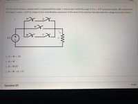
Transcribed Image Text:pts
For the circuit shown, a closed switch is represented by a logic 1, and an open switch by a logic 0. If v = 5 V across the resistor Ris represented
by a logic 1, and v = 0 V by a logic 0, then what Boolean expression of the state of the switches best describes the voltage across the resistor?
W
W
W
Y
+
5 V
OR= W +XY
OR= W
OR= WXY
OR=W (X+ Y)
4 pts
Question 25
Expert Solution
This question has been solved!
Explore an expertly crafted, step-by-step solution for a thorough understanding of key concepts.
This is a popular solution
Trending nowThis is a popular solution!
Step by stepSolved in 2 steps with 1 images

Knowledge Booster
Learn more about
Need a deep-dive on the concept behind this application? Look no further. Learn more about this topic, electrical-engineering and related others by exploring similar questions and additional content below.Similar questions
- Basic Logic Gate and Circuit Theory 1-30. Calculate Vo given that the reverse bias satu- ration current Is = 1 nA and you are at room temperature. Vo Rs D₁ A 16 nA D₂arrow_forwardUsing LogicWorks construct two circuits to the following functions : F1 = x+x'y F2 = x+yarrow_forwardQ2: Can you answer this question with clearly showing your workarrow_forward
- Clock X C A D JEST B Y FIGURE 4-49 Circuit for Problem 4-11, Problem 4-40, Problem 4-41, Problem 4-49, Problem 4-50, and Problem 4-59 4-11. A sequential circuit has two D flip-flops, one input X, and one output Y. The logic diagram of the circuit is shown in Figure 4-49. Derive the state table and state diagram of the circuit.arrow_forwardQ4arrow_forward2. Explain which of the following instructions are invalid? State the invalidation reason and give the correct form for invalid instructions: a. MOV DL,AX b. MOV ES,CX c. MOV [BX],[2000] d. MOV BX,[AX] e. MOV CL,[BL+200] f. MOV 1234,DX g. MOV CH,[BX+SI+300] h. MOV DS,[SI+DI-5] i. MOV [4500],1234 j. MOV 200,[300]arrow_forward
- What logic function is performed by this circuit? VDD a. O d. e. A b. None OC AB AB A+B A+B O f. B AB M₁ M₂ M3 M4 F M5arrow_forwardFor the circuit shown, a closed switch is represented by a logic 1, and an open switch by a logic 0. If v =5 V across the resistor R is represented by a logic 1, and v = 0 V bya logic 0, then what Boolean expression of the state of the switches best describes the voltage across the resistor? W + 5 V OR= X (Y +W) OR=WXY OR=W+ X +Y OR=XY +WX+ WYarrow_forwardQ1: Can you clearly show the answer to both parts of this questionarrow_forward
arrow_back_ios
arrow_forward_ios
Recommended textbooks for you
 Introductory Circuit Analysis (13th Edition)Electrical EngineeringISBN:9780133923605Author:Robert L. BoylestadPublisher:PEARSON
 Delmar's Standard Textbook Of ElectricityElectrical EngineeringISBN:9781337900348Author:Stephen L. HermanPublisher:Cengage Learning
 Programmable Logic ControllersElectrical EngineeringISBN:9780073373843Author:Frank D. PetruzellaPublisher:McGraw-Hill Education
 Fundamentals of Electric CircuitsElectrical EngineeringISBN:9780078028229Author:Charles K Alexander, Matthew SadikuPublisher:McGraw-Hill Education
 Electric Circuits. (11th Edition)Electrical EngineeringISBN:9780134746968Author:James W. Nilsson, Susan RiedelPublisher:PEARSON
 Engineering ElectromagneticsElectrical EngineeringISBN:9780078028151Author:Hayt, William H. (william Hart), Jr, BUCK, John A.Publisher:Mcgraw-hill Education,

Introductory Circuit Analysis (13th Edition)
Electrical Engineering
ISBN:9780133923605
Author:Robert L. Boylestad
Publisher:PEARSON

Delmar's Standard Textbook Of Electricity
Electrical Engineering
ISBN:9781337900348
Author:Stephen L. Herman
Publisher:Cengage Learning

Programmable Logic Controllers
Electrical Engineering
ISBN:9780073373843
Author:Frank D. Petruzella
Publisher:McGraw-Hill Education

Fundamentals of Electric Circuits
Electrical Engineering
ISBN:9780078028229
Author:Charles K Alexander, Matthew Sadiku
Publisher:McGraw-Hill Education

Electric Circuits. (11th Edition)
Electrical Engineering
ISBN:9780134746968
Author:James W. Nilsson, Susan Riedel
Publisher:PEARSON

Engineering Electromagnetics
Electrical Engineering
ISBN:9780078028151
Author:Hayt, William H. (william Hart), Jr, BUCK, John A.
Publisher:Mcgraw-hill Education,