Structural Analysis
6th Edition
ISBN: 9781337630931
Author: KASSIMALI, Aslam.
Publisher: Cengage,
expand_more
expand_more
format_list_bulleted
Concept explainers
Question
thumb_up100%
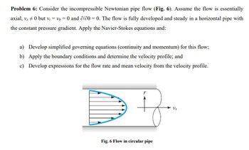
Consider the incompressible Newtonian pipe flow (Fig. 6). Assume the flow is essentially
axial, vz ≠ 0 but vr = v = 0 and ∂/∂ = 0. The flow is fully developed and steady in a horizontal pipe with
the constant pressure gradient. Apply the Navier-Stokes equations and:

Transcribed Image Text:### Problem 6: Incompressible Newtonian Pipe Flow
Consider the incompressible Newtonian pipe flow (Fig. 6). Assume the flow is essentially axial, \( v_z \neq 0 \) but \( v_r = v_\theta = 0 \) and \(\partial/\partial \theta = 0\). The flow is fully developed and steady in a horizontal pipe with the constant pressure gradient. Apply the Navier-Stokes equations and:
a) Develop simplified governing equations (continuity and momentum) for this flow;
b) Apply the boundary conditions and determine the velocity profile; and
c) Develop expressions for the flow rate and mean velocity from the velocity profile.
### Diagram Explanation
**Fig. 6: Flow in Circular Pipe**
The diagram illustrates a circular pipe with flow moving in the axial direction. The arrows indicate the direction and relative magnitude of the velocity, \( v_z \), which varies across the radius of the pipe. The centerline indicates the direction of maximum velocity, while the velocity decreases towards the pipe walls. The pipe is depicted in cross-section, showing the symmetrical nature of the flow profile.
Expert Solution
This question has been solved!
Explore an expertly crafted, step-by-step solution for a thorough understanding of key concepts.
Step by stepSolved in 5 steps with 1 images

Knowledge Booster
Learn more about
Need a deep-dive on the concept behind this application? Look no further. Learn more about this topic, civil-engineering and related others by exploring similar questions and additional content below.Similar questions
- Consider the two-dimensional flow of an inviscid, incompressible fluid described by the superposition of a parallel flow of velocity V0, a source of strength q, and a sink of strength −q, separated by a distance b in the direction of the parallel flow, the source being upstream of the sink. (a) Find the resultant stream function and velocity potential. (b) Sketch the streamline pattern. (c) Find the location of the upstream stagnation point relative to the source.arrow_forwardIn using Darcy-Weisbach equation for flow in a pipe, the friction factor is misjudged by + 25%. The resulting error in the estimated discharge Q isarrow_forward6 Consider a fully developed laminar flow of a fluid through 8027 m long and 4 cm diameter horizontal and circular pipe. The dynamic density and the viscosity of the fluid are 1252 kg/m³ and 0.3073 kg/(m.s). The velocity profile at a cross-section is given by: u(r)= 6[1 − ( 7 )²] - m/s Where r is the axial distance from the centre and R is the radius of the pipe. Determine the following: (i) (ii) the maximum velocity at a cross-section of the pipe, Umax the average velocity at a cross-section of the pipe, Vave the volume flow rate, Q (iv) Reynolds number, Re (v) friction factor, f (vi) head loss, hi (vii) pressure loss, AP (viii) pumping power required, (ix) for the same pumping power, the percentage decrease of the flow rate if the pipe is inclined 10° upward (assume the head loss, hò, calculated in part (vi) does not change) Useful formulae: 64 f Re h₂ = f ( =) ( 2² ) 2g =arrow_forward
arrow_back_ios
arrow_forward_ios
Recommended textbooks for you

 Structural Analysis (10th Edition)Civil EngineeringISBN:9780134610672Author:Russell C. HibbelerPublisher:PEARSON
 Principles of Foundation Engineering (MindTap Cou...Civil EngineeringISBN:9781337705028Author:Braja M. Das, Nagaratnam SivakuganPublisher:Cengage Learning
 Fundamentals of Structural AnalysisCivil EngineeringISBN:9780073398006Author:Kenneth M. Leet Emeritus, Chia-Ming Uang, Joel LanningPublisher:McGraw-Hill Education
 Traffic and Highway EngineeringCivil EngineeringISBN:9781305156241Author:Garber, Nicholas J.Publisher:Cengage Learning


Structural Analysis (10th Edition)
Civil Engineering
ISBN:9780134610672
Author:Russell C. Hibbeler
Publisher:PEARSON

Principles of Foundation Engineering (MindTap Cou...
Civil Engineering
ISBN:9781337705028
Author:Braja M. Das, Nagaratnam Sivakugan
Publisher:Cengage Learning

Fundamentals of Structural Analysis
Civil Engineering
ISBN:9780073398006
Author:Kenneth M. Leet Emeritus, Chia-Ming Uang, Joel Lanning
Publisher:McGraw-Hill Education


Traffic and Highway Engineering
Civil Engineering
ISBN:9781305156241
Author:Garber, Nicholas J.
Publisher:Cengage Learning