
Introductory Circuit Analysis (13th Edition)
13th Edition
ISBN: 9780133923605
Author: Robert L. Boylestad
Publisher: PEARSON
expand_more
expand_more
format_list_bulleted
Related questions
Concept explainers
Question
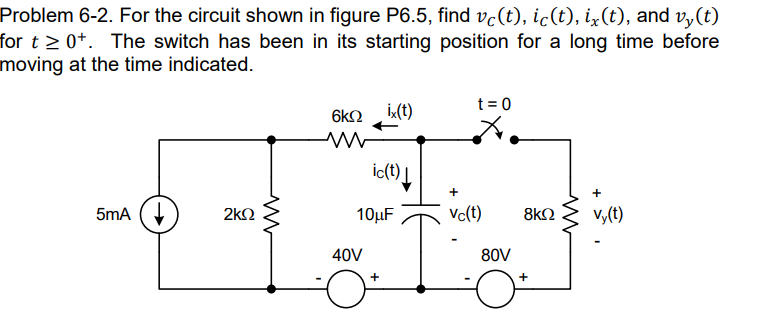

Transcribed Image Text:**Problem 6-2: Analysis of a Circuit with Capacitor and Switch Dynamics**
**Objective:**
Determine the functions \( v_c(t) \), \( i_c(t) \), \( i_x(t) \), and \( v_y(t) \) for \( t \geq 0^+ \).
**Circuit Description:**
- A current source provides 5 mA.
- A 2 kΩ resistor is connected in series with the current source.
- The circuit features two voltage sources: one providing 40 V and another one providing 80 V.
- A capacitor of 10 µF is connected parallel to the 40 V source, with the voltage across it labeled as \( v_c(t) \).
- The circuit includes a 6 kΩ resistor where the current \( i_x(t) \) is flowing through.
- An open switch is present in series with an 8 kΩ resistor. This switch is initially closed and labeled as \( t=0 \). Upon opening at \( t = 0 \), it affects the path of the current.
- The current through the capacitor is denoted by \( i_c(t) \).
- The voltage across the 8 kΩ resistor is labeled \( v_y(t) \).
**Analysis Scenario:**
The switch in the circuit has been in the closed position for a significant time period, ensuring that the circuit reaches a steady state before the switch is opened at \( t = 0 \).
**Instructions:**
- Find \( v_c(t) \), the voltage across the capacitor.
- Find \( i_c(t) \), the current through the capacitor.
- Determine \( i_x(t) \), the current through the 6 kΩ resistor.
- Calculate \( v_y(t) \), the voltage across the 8 kΩ resistor for \( t \geq 0^+ \).
Understanding the transition of the circuit from steady state to dynamic behavior when the switch is opened requires solving the above parameters using basic principles of circuit analysis such as Ohm’s Law, Kirchhoff's Laws, and properties of capacitors.
Expert Solution
This question has been solved!
Explore an expertly crafted, step-by-step solution for a thorough understanding of key concepts.
Step 1: State the given data.
VIEW Step 2: Finding the initial conditions.
VIEW Step 3: Finding the time constant for t > 0.
VIEW Step 4: Finding the vc(t) as 't' tends to infinity.
VIEW Step 5: Finding the expression of the voltages vc(t), vy(t).
VIEW Step 6: Finding the expression of the currents ic(t), ix(t).
VIEW Solution
VIEW 
Step by stepSolved in 7 steps with 5 images

Knowledge Booster


Learn more about
Need a deep-dive on the concept behind this application? Look no further. Learn more about this topic, electrical-engineering and related others by exploring similar questions and additional content below.Similar questions
- 6-38 The switch in the circuit of Figure P6-38 is closed at t = 0, and the circuit is ini- tially relaxed. Determine the current i(t). FIGURE P6-38 100 cos 5000f 0.2 H 1.2 k ww 190² 0.2 μFarrow_forward-2•t mA (tis in 6.32 In the circuit below, the source current function is ig = 4.0.e second in this equation), and the voltage across each capacitor is equal to zero at t = 0. The capacitors = 21 UF , C2 = 13 UF , and C3 = 14 UF. Determine the v2 (in V) when t = 1.3 s. Please pay attention: the numbers may change since they are randomized. Your answer must include 1 place after the decimal point. %3D %3D %3D C3 + is V2 C2 10 Ω Your Answer: Answerarrow_forwardA circuit consists of an inductor and two capacitors all in series. The inductor has a resistance of 10Ω and an inductance of 159μH. The first capacitor has 200pF and the second is a variable capacitor with a wide capacitive range. This series circuit is connected to a 50mV sinusoidal supply of fixed frequency 1MHz. (i) What value of the variable capacitance will be required for a resonance condition (give the answer in pF)?arrow_forward
- Note this circuit below is of 4th order. Plot the voltages across capacitor C1 and C2. On a separate graph, plot the currents through the inductors.arrow_forwardAn alternating current E(t)=120sin(12t) has been running through a simple circuit for a long time. The circuit has an inductance of L= 0.44 henrys, a resistor of R=7 ohms, and a capacitor of capacitance C= 0.032 farads.What is the amplitude of the current I?arrow_forward(c) Find the equivalent capacitance CE of the circuit shown in figure 6. C'1 C2 201 a b Figure 6. 202arrow_forward
arrow_back_ios
arrow_forward_ios
Recommended textbooks for you
- Introductory Circuit Analysis (13th Edition)Electrical EngineeringISBN:9780133923605Author:Robert L. BoylestadPublisher:PEARSON
 Delmar's Standard Textbook Of ElectricityElectrical EngineeringISBN:9781337900348Author:Stephen L. HermanPublisher:Cengage Learning
 Programmable Logic ControllersElectrical EngineeringISBN:9780073373843Author:Frank D. PetruzellaPublisher:McGraw-Hill Education
  Fundamentals of Electric CircuitsElectrical EngineeringISBN:9780078028229Author:Charles K Alexander, Matthew SadikuPublisher:McGraw-Hill Education
 Electric Circuits. (11th Edition)Electrical EngineeringISBN:9780134746968Author:James W. Nilsson, Susan RiedelPublisher:PEARSON
 Engineering ElectromagneticsElectrical EngineeringISBN:9780078028151Author:Hayt, William H. (william Hart), Jr, BUCK, John A.Publisher:Mcgraw-hill Education,
Introductory Circuit Analysis (13th Edition)
Electrical Engineering
ISBN:9780133923605
Author:Robert L. Boylestad
Publisher:PEARSON
Delmar's Standard Textbook Of Electricity
Electrical Engineering
ISBN:9781337900348
Author:Stephen L. Herman
Publisher:Cengage Learning
Programmable Logic Controllers
Electrical Engineering
ISBN:9780073373843
Author:Frank D. Petruzella
Publisher:McGraw-Hill Education
Fundamentals of Electric Circuits
Electrical Engineering
ISBN:9780078028229
Author:Charles K Alexander, Matthew Sadiku
Publisher:McGraw-Hill Education
Electric Circuits. (11th Edition)
Electrical Engineering
ISBN:9780134746968
Author:James W. Nilsson, Susan Riedel
Publisher:PEARSON
Engineering Electromagnetics
Electrical Engineering
ISBN:9780078028151
Author:Hayt, William H. (william Hart), Jr, BUCK, John A.
Publisher:Mcgraw-hill Education,