Question
Need a good explanation and step by step solution for this problem, not just copied out of the solutions manual.

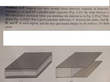
Transcribed Image Text:**Problem 4.19:** Suppose you have enough linear dielectric material, of dielectric constant \( \epsilon_r \), to *half-fill* a parallel-plate capacitor (Fig. 4.25). By what fraction is the capacitance increased when you distribute the material as in Fig. 4.25(a)? How about Fig. 4.25(b)? For a given potential difference \( V \) between the plates, find \( E \), \( D \), and \( P \), in each region, and the free and bound charge on all surfaces, for both cases.
**Explanation of Figures:**
- **Figure 4.25(a):** The dielectric material is inserted between the plates, with half of the capacitor volume filled from one side of the plates to the other.
- **Figure 4.25(b):** The dielectric material is inserted with half of the capacitor volume filled along the entire area, with the plates parallel but only extending halfway.
In both diagrams, the capacitor plates are shown as parallel plates with the dielectric material filling half the volume, illustrated to help understand different spatial arrangements of dielectric insertion.
For educational purposes, the problem involves understanding how the arrangement of a dielectric within a capacitor affects overall capacitance, electric field (\( E \)), electric displacement (\( D \)), polarization (\( P \)), and charge distribution.
Expert Solution
This question has been solved!
Explore an expertly crafted, step-by-step solution for a thorough understanding of key concepts.
This is a popular solution
Trending nowThis is a popular solution!
Step by stepSolved in 8 steps

Knowledge Booster
Similar questions
- Modern PhysicsDerive the equation above to form the answer highlighted. Show the solution. Derive the equation ∆t = 2/cv √(∆tnot/2)² + (V∆t/2)² and it should come up with that highlighted answer below. So it means that you need to show the process of the solution on how that equation comes up with that highlighted answer.arrow_forwardS Can 6 PAR к Торс K Unit K In x K Moti = Cop K Unit S Spee S Topo S Math Micr eb.kamihq.com/web/viewer.html?source-filepicker&document_identifier=137VZR5BZOVSAIMOA55WU555_CvJ9NacO + 100 P e Interpreting Graphs Answer the questions following the graphs on each side Dietance va. Time 2 7 10 11 12 13 14 Time in soconds 1. From 1 second to 2 seconds, how fast is the object traveling. (Take the difference in distance and divide it by the time in between the 2 distances) 2. Is the object going as fast between 9 and 12 seconds as it is between 1 and 4 seconds? How can you tell? 3. What is the motion of the object between 4 and 6 seconds? acerarrow_forwardthe average density of an atom is approximately 103 kg/m3. The nucleus of an atom has a radius about 10-5 times that of the entire atom, and contains nearly all the mass of the atom. What is the approximate density, in kilograms per cubic meter, of a nucleus?arrow_forward
- A hot tub with a surface area of 28 ft2 is filled with water to a depth of 29 in . Hint: volume is calculated as area × height (A × h). A) What is the volume of water in the tub, in liters? Express your answer to two significant figures and include the appropriate units. B) How many kilojoules are needed to heat the water from 59∘F to 103 ∘F? Express your answer to two significant figures and include the appropriate units. C) If the hot-tub heater provides 5900 kJ/min, how long, in hours, will it take to heat the water in the hot tub from 59∘F to 103∘F? Express your answer to two significant figures and include the appropriate units.arrow_forwardA bacteria colony which is unrestricted in its growth will grow out in a circular manner. The population ?(?) of the colony at time t is directly proportional to the area of the circle. Suppose that a particular bacteria grows in such a way that the population is 1.3 times larger each day, and that initially (t=0) the colony has a diameter of 4 centimeter and a population of 7 million. a) Find the Population and Diameter of the colony on the fifth day. b) Find the Rate of Change of the Population and Diameter of the colony on the fifth day. c) Unrestricted growth models are often impractical as values will quickly become unreasonable. On what day does our model predict that the area of the bacteria colony will be 1 square mile?arrow_forward
arrow_back_ios
arrow_forward_ios