Related questions
Question

Transcribed Image Text:Problem 4
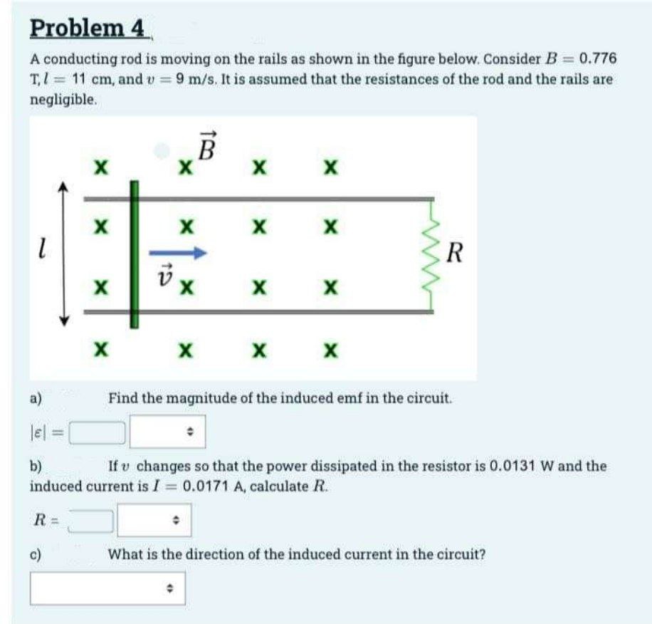
A conducting rod is moving on the rails as shown in the figure below. Consider B = 0.776
T₁/= 11 cm, and v= 9 m/s. It is assumed that the resistances of the rod and the rails are
negligible.
1
R=
X
c)
X
X
B
X
X
X
X
X X
X X
X X X X
R
a)
|el =
b)
If u changes so that the power dissipated in the resistor is 0.0131 W and the
induced current is I = 0.0171 A, calculate R.
Find the magnitude of the induced emf in the circuit.
What is the direction of the induced current in the circuit?
Expert Solution
This question has been solved!
Explore an expertly crafted, step-by-step solution for a thorough understanding of key concepts.

Step by stepSolved in 3 steps with 11 images

Knowledge Booster

Similar questions
- A power plant needs to generate Po= 340MW of power for a city 10km away. The city power outlets need to operate at 120V. Part A One idea might be to run the power lines at 120V so homes can directly tap into the power lines. What is the current needed to do this? (Hint: use P-IV). |VD ΑΣΦ ? |= Amps Submit Request Answer Part B The power lines have a resistance of 0.2 0/km. What are the ohm-ic losses (L.e. the power dissipated via resistance) in the power lines to transport the energy from the power plant to the city if we use the current from 1²R part (a)? (HINT: compute the total resistance of the power lines and then use P VG ΑΣΦ 5 A W P=arrow_forward3Ω a ↓ 2.02 12 V ww+H T Travel. I ww 4Ω 4V b 702arrow_forwardPlease don't provide handwritten solution ...arrow_forward
- Problem4. Find Rz in the following circuit to achieve maximum power transfer to it, and the value of the maximum power transfer. + Vx R2 k2 1 kN ŽRL +, 12 V +, 2 Vxarrow_forwardIn the figure R1 = 10.7 kΩ, R2 = 14.7 kΩ, C = 0.405 μF, and the ideal battery has emf ε = 25.0 V. First, the switch is closed a long time so that the steady state is reached. Then the switch is opened at time t = 0. What is the current in resistor 2 at t = 3.80 ms?arrow_forwardB/ If a conductor with current of 250 mA passing through it and converts of 20J of electrical energy into heat in 30 seconds. What the potential drop across the conductor? 1-250MA W=20 t=30 75arrow_forward
- If the switch (S) in the figure is closed for a very long time, what is the charge on the capacitor? Use an emf of 20 V, R1 = 100 Ω and C1 = 20 μF.arrow_forwardThe circuit shown has two resistors, with R1 > R2 .Which resistor dissipates the larger amount of power? Explain.arrow_forwardG₁ R₁ www R3 The figure above shows a circuit with R₁ = C₂ = 10.0μF, and the ideal battery has emf & state. = 5.00, R₂ 20.0 V. R₂ = www C₂ 10.0Ω, R3 15.092, C₁ 5.00μF, Assume that the circuit is in a steady = = (a) Explain what we mean when we say that "a circuit is in a steady state," and what this assumption specifically implies for the circuit under consideration. (b) Find the current through the battery. (c) Find the voltage across C₁. (d) Find the voltage across C₂.arrow_forward
arrow_back_ios
arrow_forward_ios