Introductory Circuit Analysis (13th Edition)
13th Edition
ISBN: 9780133923605
Author: Robert L. Boylestad
Publisher: PEARSON
expand_more
expand_more
format_list_bulleted
Question
Hello I need help with part A, Part B and Part C because I don't know what I keep doing wrong. Can you label which one is which

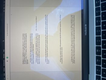
Transcribed Image Text:## Problem 2:
### Scenario:
A lightbulb is in series with a resistor \( R = 2.0 \, \Omega \). The lightbulb dissipates \( P = 10 \, \text{W} \) when this series circuit is connected to a \( \Delta V_{\text{bat}} = 9.0 \, \text{V} \) battery. The task is to determine the current through the lightbulb.
### Steps:
1. **Diagram Construction:**
- **Task:** Draw the diagram that represents this electric circuit.
- **Guideline:** Use a library of basic symbols for electric circuit drawings as referenced in paragraph 28.1 of the textbook.
2. **Resistance Expression:**
- **Objective:** Express the resistance of the lightbulb, \( R_{\text{lb}} \), in terms of the power it dissipates, \( P \), and the current in the circuit, \( I \).
- **Note:** Do not plug in the numerical values yet; just write down the formula.
3. **Kirchhoff’s Loop Law:**
- **Instruction:** Write down the Kirchhoff’s loop law for this circuit. Formulate this equation in symbolic form. The coefficients must be functions of \( \Delta V_{\text{bat}} \), \( R \), and \( P \).
4. **Numerical Solution:**
- **Task:** Plug in the numerical values of the parameters and solve the quadratic equation for \( I \). This will yield two possible values for the current.
5. **Analysis of Results:**
- **Consideration:** The two values of \( I \) relate to different lightbulbs (a single lightbulb with a fixed resistance uniquely determines the current). Determine the two possible nominal power ratings of the lightbulbs that satisfy the problem's conditions.
### Diagram Explanation:
- **Fig. 2:** Represents the scheme for Problem 2. Ensure to replicate the required elements and symbols accurately, as instructed in the task.
This structured breakdown allows students to approach the problem step-by-step, encouraging understanding of both theoretical and practical applications of circuit analysis.
Expert Solution
This question has been solved!
Explore an expertly crafted, step-by-step solution for a thorough understanding of key concepts.
This is a popular solution
Trending nowThis is a popular solution!
Step by stepSolved in 3 steps with 1 images

Knowledge Booster
Learn more about
Need a deep-dive on the concept behind this application? Look no further. Learn more about this topic, electrical-engineering and related others by exploring similar questions and additional content below.Similar questions
Recommended textbooks for you
 Introductory Circuit Analysis (13th Edition)Electrical EngineeringISBN:9780133923605Author:Robert L. BoylestadPublisher:PEARSON
 Delmar's Standard Textbook Of ElectricityElectrical EngineeringISBN:9781337900348Author:Stephen L. HermanPublisher:Cengage Learning
 Programmable Logic ControllersElectrical EngineeringISBN:9780073373843Author:Frank D. PetruzellaPublisher:McGraw-Hill Education
 Fundamentals of Electric CircuitsElectrical EngineeringISBN:9780078028229Author:Charles K Alexander, Matthew SadikuPublisher:McGraw-Hill Education
 Electric Circuits. (11th Edition)Electrical EngineeringISBN:9780134746968Author:James W. Nilsson, Susan RiedelPublisher:PEARSON
 Engineering ElectromagneticsElectrical EngineeringISBN:9780078028151Author:Hayt, William H. (william Hart), Jr, BUCK, John A.Publisher:Mcgraw-hill Education,

Introductory Circuit Analysis (13th Edition)
Electrical Engineering
ISBN:9780133923605
Author:Robert L. Boylestad
Publisher:PEARSON

Delmar's Standard Textbook Of Electricity
Electrical Engineering
ISBN:9781337900348
Author:Stephen L. Herman
Publisher:Cengage Learning

Programmable Logic Controllers
Electrical Engineering
ISBN:9780073373843
Author:Frank D. Petruzella
Publisher:McGraw-Hill Education

Fundamentals of Electric Circuits
Electrical Engineering
ISBN:9780078028229
Author:Charles K Alexander, Matthew Sadiku
Publisher:McGraw-Hill Education

Electric Circuits. (11th Edition)
Electrical Engineering
ISBN:9780134746968
Author:James W. Nilsson, Susan Riedel
Publisher:PEARSON

Engineering Electromagnetics
Electrical Engineering
ISBN:9780078028151
Author:Hayt, William H. (william Hart), Jr, BUCK, John A.
Publisher:Mcgraw-hill Education,