Introductory Circuit Analysis (13th Edition)
13th Edition
ISBN: 9780133923605
Author: Robert L. Boylestad
Publisher: PEARSON
expand_more
expand_more
format_list_bulleted
Question

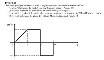
Transcribed Image Text:Problem 1:
The message signal as below is used to angle modulate a carrier c(t) = 100cos4000лt.
(a) (5pts) Determine the peak-frequency deviation with k=2 using FM.
(b) (5pts) Determine the peak-phase deviation with k₂ =1 using PM.
(c) (10pts) If k=k=5, determine the maximum instantaneous frequency in FM and PM respectively.
(d) (10pts) Determine the phase (t) of the FM modulated signal with k₂ =2.
m(t)
3
0
-3
2
4
6
Expert Solution
This question has been solved!
Explore an expertly crafted, step-by-step solution for a thorough understanding of key concepts.
This is a popular solution
Trending nowThis is a popular solution!
Step by stepSolved in 1 steps with 2 images

Knowledge Booster
Similar questions
- Q7. Figure Q7(a) shows the spectrum of a frequency modulated waveform with a sinusoidal modulation. 12 4.8 5.0 5.2 5.4 5.6 5.8 6.0 Frequency/MHz Figure Q7: (a) Spectrum of a frequency modulated waveform with a sinusoidal modulation. (a) Is this modulated waveform described as narrowband or as wideband? (b) What is the value of the carrier frequency? (c) What is the value of the modulation frequency? (d) Determine the value of the peak frequency deviation. Plots of Bessel functions of the first kind are provided below in Figure Q7(b) to assist you. (e) Estimate the fraction of the total signal power at the carrier frequency. (f) Detection of such a frequency modulated signal is usually accomplished with the use of a discriminator. Describe the function of a discriminator. (g) What is the equivalent AM modulation index obtained if this signal in Figure Q7(a) is demodulated with a high-pass RC filter discriminator? J„(x) 1.0 0.8 0.6 0.4 0.2 -0.2 -0.4 Figure Q7: (b) Bessel functions of the…arrow_forwardI need the answer quicklyarrow_forwardIn PM, as the amplitude of the modulating signal increases, the frequency deviation will ___________. a. be infinite b. increase c. decrease d. be constantarrow_forward
- Q1-The message signal m(t) into a FM modulator with the parameter kf=25 is shown in the following figure. a) Express the FM signal in time domain.b) Calculate and plot the frequency deviation in Hz.c) Calculate and plot the phase deviation in radians.arrow_forward.arrow_forwardIn PM, as the frequency of the modulating signal decreases, the frequency deviation will ___________. a. increase b. be finite c. be constant d. decreasearrow_forward
- The message signal m(t) into a FM modulator with the parameter kf=25 is shown in the following figure.a) Express the FM signal in time domain.b) Calculate and plot the frequency deviation in Hz.c) Calculate and plot the phase deviation in radians.arrow_forwardProblem 5. A carrier wave of frequency 20 MHz is frequency-modulated by a sine-wave of amplitude 2 volts and frequency 4 kHz. The frequency sensitivity of the modulator is 10 kHz per volt. a) Determine the approximate bandwidth of the FM wave using Carson's rule. b) Repeat part (a) assuming that the amplitude of the modulating wave is doubled. c) Repeat part (a) assuming that the modulation frequency is doubled.arrow_forward4) Listen A sinewave voltage is defined by an effective voltage of 2.82Vrms. Calculation of the amplitude Vpk is performed: By multiplying Vrms by 2/Pi (=0.637). By dividing Vrms by 1.41 (square root of 2). By multiplying Vrms by 1.41 (square root of 2). By dividing Vrms by 2/Pi (=0.637). Calculation cannot be done since we do not know the frequency of the signal. O None of these statements are true. prt sc 144arrow_forward
- Identify two ways in which noise affects an FM signal. (Check all that apply.) Noise introduces amplitude variations in an otherwise constant amplitude signal. Noise introduces frequency variations in an otherwise constant frequency signal. Noise causes amplitude shift and hence phase shift. Noise causes frequency shift and hence phase shift.arrow_forwardto continue the solution.. answer part ( vi and v ) thank you ..arrow_forwardIn three-level PWM, the modulating process operates on each portion of the modulating function separately. The output peak value is still given by the depth of modulation, but the RMS value of the square wave is not Vin. Compute the THD for three-level PWM as a function of the depth of modulation (modulation index k).arrow_forward
arrow_back_ios
SEE MORE QUESTIONS
arrow_forward_ios
Recommended textbooks for you
 Introductory Circuit Analysis (13th Edition)Electrical EngineeringISBN:9780133923605Author:Robert L. BoylestadPublisher:PEARSON
 Delmar's Standard Textbook Of ElectricityElectrical EngineeringISBN:9781337900348Author:Stephen L. HermanPublisher:Cengage Learning
 Programmable Logic ControllersElectrical EngineeringISBN:9780073373843Author:Frank D. PetruzellaPublisher:McGraw-Hill Education
 Fundamentals of Electric CircuitsElectrical EngineeringISBN:9780078028229Author:Charles K Alexander, Matthew SadikuPublisher:McGraw-Hill Education
 Electric Circuits. (11th Edition)Electrical EngineeringISBN:9780134746968Author:James W. Nilsson, Susan RiedelPublisher:PEARSON
 Engineering ElectromagneticsElectrical EngineeringISBN:9780078028151Author:Hayt, William H. (william Hart), Jr, BUCK, John A.Publisher:Mcgraw-hill Education,

Introductory Circuit Analysis (13th Edition)
Electrical Engineering
ISBN:9780133923605
Author:Robert L. Boylestad
Publisher:PEARSON

Delmar's Standard Textbook Of Electricity
Electrical Engineering
ISBN:9781337900348
Author:Stephen L. Herman
Publisher:Cengage Learning

Programmable Logic Controllers
Electrical Engineering
ISBN:9780073373843
Author:Frank D. Petruzella
Publisher:McGraw-Hill Education

Fundamentals of Electric Circuits
Electrical Engineering
ISBN:9780078028229
Author:Charles K Alexander, Matthew Sadiku
Publisher:McGraw-Hill Education

Electric Circuits. (11th Edition)
Electrical Engineering
ISBN:9780134746968
Author:James W. Nilsson, Susan Riedel
Publisher:PEARSON

Engineering Electromagnetics
Electrical Engineering
ISBN:9780078028151
Author:Hayt, William H. (william Hart), Jr, BUCK, John A.
Publisher:Mcgraw-hill Education,