
Introductory Circuit Analysis (13th Edition)
13th Edition
ISBN: 9780133923605
Author: Robert L. Boylestad
Publisher: PEARSON
expand_more
expand_more
format_list_bulleted
Related questions
Concept explainers
Question
can someone show me the individual steps of how to do this problem
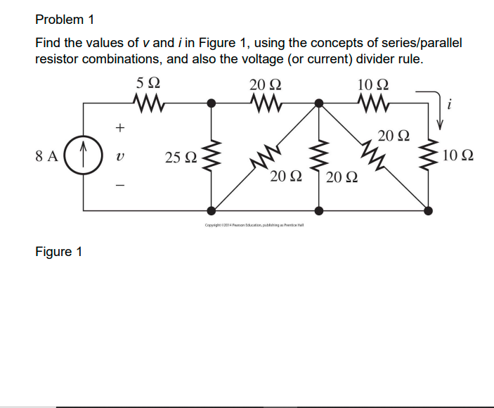

Transcribed Image Text:**Problem 1**
Find the values of \( v \) and \( i \) in Figure 1, using the concepts of series/parallel resistor combinations, and also the voltage (or current) divider rule.
**Diagram Explanation:**
The circuit in Figure 1 consists of:
- A current source of 8 A supplying current into the circuit.
- A voltage \( v \) across a path with a 5 Ω resistor in series.
- A 25 Ω resistor connected in parallel with a 20 Ω resistor combination path.
- A diamond-shaped network with:
- Two 20 Ω resistors in parallel forming one branch.
- Another two 20 Ω resistors in parallel forming another branch.
- These branches are connected in parallel to each other, with a resulting connection to a 10 Ω resistor.
- Another 10 Ω resistor in series in the path of the current \( i \).
Figure 1 illustrates how these resistors are interconnected and highlights the challenge of calculating the voltage \( v \) and the current \( i \) using resistor combination rules and divider principles.
Expert Solution
This question has been solved!
Explore an expertly crafted, step-by-step solution for a thorough understanding of key concepts.

This is a popular solution

Trending nowThis is a popular solution!

Step by stepSolved in 4 steps with 10 images

Knowledge Booster


Learn more about
Need a deep-dive on the concept behind this application? Look no further. Learn more about this topic, electrical-engineering and related others by exploring similar questions and additional content below.Similar questions
- As we know that opamps working on a dual power supply and both power supply should be in the same polarity. If the power supply is not similar in both the polarity the dc output will drift to either side depending on the higher amplitude of polarity and sometimes the case is like this offset nulling will become difficult to achieve So what is "offset nulling" ? Please explainarrow_forwardA load can be considered to be capacitive, resistive or inductive in nature.a) Discuss the differences between these types of loads. Your discussion should include the following: A description of the type of the load and why it is considered to be capacitive, resistive or inductive. How/whether energy is stored. An example where possible, and a comment on how common that type of load is. How the load will respond to a sudden removal of the driving voltage.arrow_forwardAsP plzzzzarrow_forward
Recommended textbooks for you
- Introductory Circuit Analysis (13th Edition)Electrical EngineeringISBN:9780133923605Author:Robert L. BoylestadPublisher:PEARSON
 Delmar's Standard Textbook Of ElectricityElectrical EngineeringISBN:9781337900348Author:Stephen L. HermanPublisher:Cengage Learning
 Programmable Logic ControllersElectrical EngineeringISBN:9780073373843Author:Frank D. PetruzellaPublisher:McGraw-Hill Education
  Fundamentals of Electric CircuitsElectrical EngineeringISBN:9780078028229Author:Charles K Alexander, Matthew SadikuPublisher:McGraw-Hill Education
 Electric Circuits. (11th Edition)Electrical EngineeringISBN:9780134746968Author:James W. Nilsson, Susan RiedelPublisher:PEARSON
 Engineering ElectromagneticsElectrical EngineeringISBN:9780078028151Author:Hayt, William H. (william Hart), Jr, BUCK, John A.Publisher:Mcgraw-hill Education,
Introductory Circuit Analysis (13th Edition)
Electrical Engineering
ISBN:9780133923605
Author:Robert L. Boylestad
Publisher:PEARSON
Delmar's Standard Textbook Of Electricity
Electrical Engineering
ISBN:9781337900348
Author:Stephen L. Herman
Publisher:Cengage Learning
Programmable Logic Controllers
Electrical Engineering
ISBN:9780073373843
Author:Frank D. Petruzella
Publisher:McGraw-Hill Education
Fundamentals of Electric Circuits
Electrical Engineering
ISBN:9780078028229
Author:Charles K Alexander, Matthew Sadiku
Publisher:McGraw-Hill Education
Electric Circuits. (11th Edition)
Electrical Engineering
ISBN:9780134746968
Author:James W. Nilsson, Susan Riedel
Publisher:PEARSON
Engineering Electromagnetics
Electrical Engineering
ISBN:9780078028151
Author:Hayt, William H. (william Hart), Jr, BUCK, John A.
Publisher:Mcgraw-hill Education,