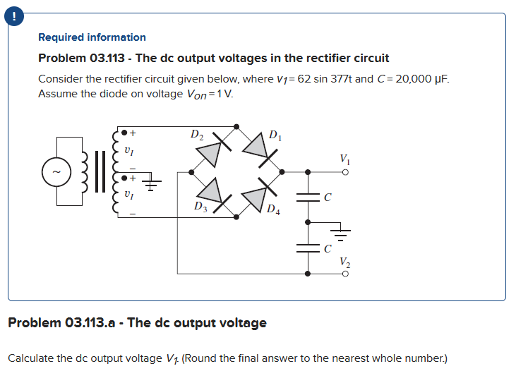
Problem 03.113 - The dc output voltages in the rectifier circuit Consider the rectifier circuit given below, where V1= 62 sin 377t and C= 20,000 μF. Assume the diode on voltage Von=1 V. ੩੩॥ VI + D₂ D3 D₁ D4 Problem 03.113.a - The dc output voltage C Calculate the dc output voltage V₁. (Round the final answer to the nearest whole number.)
Q: For the op-amp shown in the following figure, the midrange voltage gain is equal to- к на 3 kf www…
A: Given circuit is,
Q: The sinusoidal voltage, v(t) = 2 cos(2250t - 1.2) is applied to a 100 2 resistor. Find the…
A: In the given questions we need to calculate the instantaneous power.
Q: Determine period, frequency and rms value of the plotted current waveforms. Host PT ((A) 1. MA A+ ()
A: In these questions, we need to determine the time period, frequency and rms value.
Q: What are the methods for voltage regulation in a power distribution system, and how are they…
A: Voltage regulation in a power distribution system is crucial for maintaining the quality of…
Q: 5.- Design a microcontroller system to control a sprinkler controller that performs the following…
A: According to the question, we assume that your microcontroller is clocked at 10 MHz and has a 16-bit…
Q: How does the shielding in a cable affect its performance, and in what situations is it essential to…
A: Shielding in cables plays a critical role in enhancing performance and ensuring signal integrity by…
Q: Explore the concept of power quality in electrical systems and discuss the various disturbances and…
A: According to the question, we need to explore the concept of power quality in electrical systems and…
Q: What is the significance of FACTS (Flexible AC Transmission Systems) devices in optimizing power…
A: FACTS, which stands for Flexible AC Transmission Systems, are a family of power electronic devices…
Q: For the circuit shown, determine the steady- state voltage across each capacitor and the energy…
A: Here 6μF and 4 μF are in parallelAlso 12μF and 8 μF are in parallelVoltage across battery = 40 V We…
Q: Problem 3: Question Consider the circuit diagram below. Given I₁ = 2 mA and I4 = 6 mA, find the…
A:
Q: Explain the concept of power factor and its importance in electrical power systems
A: In this question, we need to explain the concept of power factor and its importance in electrical…
Q: An abrupt silicon pn junction at zero bias has dopant concentrations of Nd = 1 X 1017 cm 3 and N₂ =…
A: Given,
Q: Find the load impedance as seen from the primary side of the transformer if: a = 3, lp= 5A, and Vg =…
A: We need to find out the impedance seen from primary side of transformer.
Q: 1) Design a sequential circuit whose state table is shown below. Use JK flip-flops for the design.…
A: For the given state table the sequential circuit needs to be designed and the circuit should be…
Q: Discuss the industrial applications of IoT, especially in manufacturing and maintenance.
A: IoT has a wide range of industrial applications, with manufacturing and maintenance being two areas…
Q: onsider the B My logic circuit shown below. Which of the logic expression is correct +VDD M₂ M₁…
A: 1. For given CMOS circuit identify thelogic gate.When A=B=0: M1=M2=ON and M3=M4=OFF. Hence,
Q: What is the total resistance of the following circuit in kil ww R1 5k 10 Blank 1 www 2₂ R₂ 10ΚΩ www…
A: R1 = 5k ohmsR2 =10k ohmsR3 = 15k ohmsReq = ? ( in parallel connection )
Q: What is a microchip, and how does it differ from a semiconductor device?
A: A microchip (or integrated circuit) is a small semiconductor device that contains many tiny…
Q: 4. The current i(t) in an RL circuit is governed by the differential equation di R. + dt L =E(t) -2…
A:
Q: For the circuit: a) Find Vo if Va = 0.1V and Vb = 0.25V b) If Vb = 0.25V, how large can Va be before…
A: Given Data:An inverting Op-Amp circuit with,Inverting input voltages Inverting input resistances…
Q: How does the process technology (nanometer scale) affect the performance and power consumption of…
A: To explain:How does the process technology (nanometer scale) affect the performance and power…
Q: An LC circuit like that in the figure below consists of a 3.30-H inductor and an 830-pF capacitor…
A:
Q: How does a supervisory control and data acquisition (SCADA) system contribute to the monitoring and…
A: According to the question, we need to discuss the role of SCADA to contributing to the monitoring…
Q: Explain the concept of integrated circuits (ICs) and their relevance to microchip technology.
A: To explain:the concept of integrated circuits (ICs) and their relevance to microchip technology.
Q: 15. Write the branch current equation(s) for the following circuit. (Do not solve the equations)
A: For the given circuit the branch current equations need to be obtained and the same can be obtained…
Q: How does the shielding of a cable affect its performance in terms of signal quality and interference…
A: The shielding of a cable plays a crucial role in its performance, particularly in terms of signal…
Q: Which of the following systems will exhibit an overdamped response? O G(s) O G (s) ○ G(s) ○ G(s) = =…
A:
Q: For the iron-core transformer below if the turns ration (a)= 1/4, Ip = 3A, and Z₁ = 30. + ell N ele…
A:
Q: QUESTION 25 If the system base power is 50MVA and the base current is 1000 A, serving a load of 500…
A: 25) Z = impedanceZbase =( Vbase / Ibase ) Zbase = ( MVA rating / I2base ) Zbase = ( 50×106 / 10002 )…
Q: A multimode step index fiber has a relative refractive index difference of 1% and a core refractive…
A: Based on the given specifications for the multi-mode step-index fiber the value of the fiber core…
Q: The layout of the MCP9700-E temperature sensor are shown in Table 1. The sensor transfer function…
A: The MCP9700-E is a linear active thermistor integrated circuit. Manufactured by Microchip Technology…
Q: -WHITC (NEUTRAL) - BLACK (HOT) -RED (HOT) -BARE (BOND/GROUND) -WIRE CONNECTOR 11 (DEVICE ON A SINGLE…
A: The given figure is shown below.We need to determine the minimum size of the device box.
Q: An op amp, with the parameters indicated below, is used in a feedback configu-ration as shown. If…
A: Given:an op-amp circuit, A = 562 kV/VVofs = 22.5 mVVR = +15 V, -15 VTo find:Vout, if the input…
Q: Realize Z = A'D + A'C + AB'C'D' using four NOR gates. Step by step answer with explaination please
A: In the given questions we need to design the logic circuit diagram of the given Boolean function.
Q: Describe the concept of "fault current" in power systems. How is fault current calculated, and what…
A: Fault current in power systems refers to the flow of electrical current that occurs when a fault,…
Q: A discrete-time system with input[n] and output y[n] is governed by y[n+1] − 0.75y[n] = x[n + 1] and…
A: Given: y[n+1]−0.75y[n]=x[n+1] x[n]=cos(Ωn)We need to find the steady-state value of y[n] when Ω =…
Q: Find the numerical value of Io. Express your answer to three significant figures and include the…
A: For the given circuit the value of unknown current needs to be calculated by using the mesh…
Q: A dc source is connected to a series RLC circuit by a switch that closes at t=0, as shown in the…
A: In the given questions we need to calculate the voltage across capacitor.
Q: Q3. Use the principal of mesh-current method find the voltage Vo in the circuit shown below.…
A: Given:a circuit, we need to find voltage V0 using mesh analysis method and also we need to find the…
Q: Discuss the importance of semiconductor materials in microchip manufacturing
A: Semiconductor materials are pivotal in the electronics industry, underpinning the production of…
Q: How does the choice of cable type and quality impact signal attenuation and data integrity in…
A: The choice of cable type and quality has a significant impact on signal attenuation and data…
Q: What is a transformer, and how does it function in power transmission and distribution?
A: We need to explain:What is a transformer, and how does it function in power transmission and…
Q: 5. 70 V 3 Ohm m 8 Ohm 4 Ohm 6 Ohm 2 Ohm 2 Ohm
A:
Q: The variable dc current source in the circuit in (Figure 1) is adjusted so that the power developed…
A: In this question, we need to determine the value of idc if power developed by 15 A current source…
Q: find iL (t) and VL (t) for t >0
A: In this question, we need to determine the current i(t) and voltage v(t) for time t>0.
Q: Assume that is(t) = 4 sin(100t + 30), R = 100, R1 = 100, R2 = 50, c = 0.5mF, and L = 0.2H. A. Find…
A:
Q: The three inductors in the circuit in (Figure 1) are connected across the terminals of a black box…
A: Given:a circuit, with, we need to find:.
Q: The low frequency behavior of an amplifier is represented by the following Laplace transform: (st…
A: In this question, we need to determine the phase angle for decreasing frequencies below 10 rad/s…
Q: Discuss the evolution of microchip technology over the years. How have advances in microchip design…
A: To discuss:the evolution of microchip technology over the years. How have advances in microchip…
Q: Explain the concept of Industrial IoT (IIoT) and its applications in manufacturing and industry…
A: The concept of industrial IoT needs to be briefed and it's applications in manufacturing and…
Trending now
This is a popular solution!
Step by step
Solved in 3 steps with 4 images
- What is CEMF?Calculate the average value of the output voltage for ? = 60 ° of a three-phase full-wave thyristor rectifier operating on a network with phase neutral voltage of 100V.A sinusoidal voltage of 48v, 60 Hz is applied to a half-wave rectifier with dynamic resistance of the diode of .001ohms turns ratio (3:1). Calculate the DC and RMS currents flowing through the load(R=210 ohms). Also calculate the dc output power developed, ac – input power supplied, rectification efficiency, and ripple factor.
- The secondary input voltage to a single phase diode bridge rectifier is 50V, 50Hz, and the load can be replaced by a resistance of value 20ohms (a) Sketch a well labelled circuit of the converter described above. (b) Sketch the waveforms for the input voltage, output voltage, output current, and output current (c) Derive an equation for average output voltage and calculate for output dc voltage (d) Calculate the ripple factor of the output voltage (e) Transformer utilization factor (h) How can the ripple be improvedA schematic design of a full-wave bridge type power supply is given below. Provide the appropriate values for the inductors, diodes, capacitor and resistors, such that the output DC voltage is 6.2 V and the max. output power for the load resistance is 20 mW (percentage error for output voltage and output power is 2%). AC voltage source: Amplitude=311.13, Freq=60, DC offset= 0. For the rectifier part, choose diodes with an appropriate PIV rating. Show all the formulas and computations involved in acquiring the values for the inductors, diodes, capacitor and resistors. In choosing your Zener diode, consider the output voltage and the output current. Note that the output current should be the minimum Zener current. For the value of the series resistor RS, choose a lower value for less ripple but always consider the required output voltage. The ripple voltage peak-to-peak value should be less than or equal to 1% of the required output voltage. Use the formula below for choosing the value…A fully controlled three-phase rectifier bridge circuit supplies a dc load of 300V,60A, from 415V 3-phase ac supply via delta-star transformer. (i) Determine the required thyristor and transformer specifications. (ii) Draw the load and thyristor voltages when firing angle alpha = 60°. (ii) If a commutating diode is placed across the load, determine the FWD specification and then calculate the average load voltage and FWD average current when firing angle alpha = 45°
- Q.1 A single-phase diode bridge rectifier is connected to a grid with rms voltage V, 230V at 50 Hz. Assume that the load is highly inductive, so it could be represented by a constant dc current, Id = 10A. a) Sketch the load voltage and find the average voltage of the load? b) Sketch the source current (grid. AC side) and find the rms value of the source current? c) Determine the fundamental source current and the first three harmonics? Assume Ish_rms ³ 0.91a/h for odd hand 0 otherwise?Q ) For the full- wave uncontrolled rectifier circuit supplying a series resistive Thesupply voltage is v =300 sinωt , the supply frequency is 50 Hz and the loadparameter values are: R =05 Ω,a) Sketch the diagram of electrical circuitb) Sketch the load voltage and current waveforms .c) Calculate the load currentd) Calculate the average DC load voltage Vdc .e) Calculate the supply power to the loaQ: A single-phase, full-wave diode bridge is used to supply power to aresistive load of value R = 75 Ω. If the supply voltage is sinusoidal,Vs = 400 sin ωt, Calculate: 1) the average and rms values of the load current. (IL rms), (Idc) 2)the ripple factor (RF)for the load current wave operation.
- 1. A single-phase, 120V, 50Hz supply is connected to a controlled half-wave thyristor rectifier and series R-L load consisting of a resistor R of 350 ohms and inductor L of 150mH. The thyristor firing angle is 65 degrees. Assume the diode and thyristor are ideal. i) calculate the dc load voltage VDC and the load dc current IDC. ii) briefly explain why a freewheeling diode is often connected in parallel to an R-L connected load in rectifier circuits4670V = VsR = 200kΩ C = 0.1μF Consider the circuit and parameters illustrated above. If a derating factor of 12% is sugested then calculate, 12) the maximum reverse voltage rating of the diodes; 13) the string efficiency of this arrangement; 14) the maximum difference in leakage current of the diodes; 15) the maximum difference in stored charge of the diodes.Consider the full-wave rectifier circuit shown below, where• vS(t) is a sinusoidal signal with a peak value (Vs = 5 V).• Diodes are modelled using constant voltage model with VDO = 0.7 V• The ac line voltage has an rms value of 120 V and a frequency (f) = 60 Hza) Calculate the transformer turns ratio. b) Plot in the same graph signal vS(t) and the output signal vO(t) versus time (t) (show all details including amplitudes, time instances, etc.) c) Calculate the rms value of the output signal vO(t). (hint: sin2(x) = 0.5(1- cos(2x))) d) If a capacitor C=3.58 F is connected across R = 10 k, repeat (b) in a new graph