
Structural Analysis
6th Edition
ISBN: 9781337630931
Author: KASSIMALI, Aslam.
Publisher: Cengage,
expand_more
expand_more
format_list_bulleted
Related questions
Concept explainers
Question
Please answer the problem attached image.
Hint: 1. a=293.27mm, b=970.63×10^6mm^4
2. 48.857×10^6mm^4
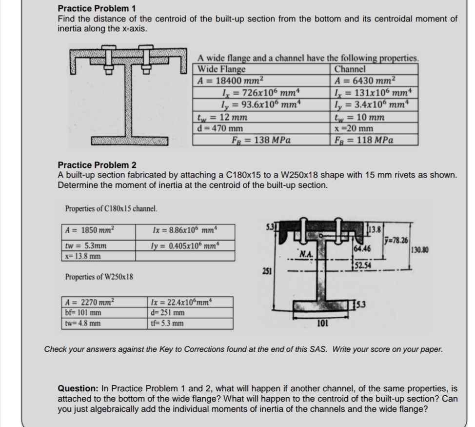

Transcribed Image Text:Practice Problem 1
Find the distance of the centroid of the built-up section from the bottom and its centroidal moment of
inertia along the x-axis.
Properties of C180x15 channel.
A = 1850 mm²
tw = 5.3mm
x= 13.8 mm
Properties of W250x18
A wide flange and a channel have the following properties.
Wide Flange
Channel
A = 18400 mm²
A = 6430 mm²
Ix=131x106 mmª
ly = 3.4x106 mm¹
tw = 10 mm
x =20 mm
FB = 118 MPa
A = 2270 mm²
bf= 101 mm
tw= 4.8 mm
Practice Problem 2
A built-up section fabricated by attaching a C180x15 to a W250x18 shape with 15 mm rivets as shown.
Determine the moment of inertia at the centroid of the built-up section.
tw = 12 mm
d=470 mm
Ix = 726x106 mmª
ly = 93.6x106 mmª
Ix=8.86x106 mm¹
ly= 0.405x105 mm
Ix= 22.4x106mm*
d=251 mm
tf=5.3 mm
FB = 138 MPa
5.31
251
N.A.
101
113.8
64.46
52.54
115.3
=78.26
130.80
Check your answers against the Key to Corrections found at the end of this SAS. Write your score on your paper.
Question: In Practice Problem 1 and 2, what will happen if another channel, of the same properties, is
attached to the bottom of the wide flange? What will happen to the centroid of the built-up section? Can
you just algebraically add the individual moments of inertia of the channels and the wide flange?
Expert Solution
This question has been solved!
Explore an expertly crafted, step-by-step solution for a thorough understanding of key concepts.

This is a popular solution

Trending nowThis is a popular solution!

Step by stepSolved in 2 steps with 4 images

Knowledge Booster


Learn more about
Need a deep-dive on the concept behind this application? Look no further. Learn more about this topic, civil-engineering and related others by exploring similar questions and additional content below.Similar questions
- 1. Draw the front view in the direction of F and the top view in the direction T of the given machine element using first angle projection with scale 1:1. (Front view-4, Top view-4, Dimensioning-2) 100% 1/1 T 25 30 25 40 20 030 25 80 25 50arrow_forwardWhere has the 311.2mm and 327.1mm and 15.8mm Come from ? That's what I don't understand.arrow_forward
Recommended textbooks for you
 Structural Analysis (10th Edition)Civil EngineeringISBN:9780134610672Author:Russell C. HibbelerPublisher:PEARSON
 Principles of Foundation Engineering (MindTap Cou...Civil EngineeringISBN:9781337705028Author:Braja M. Das, Nagaratnam SivakuganPublisher:Cengage Learning
 Fundamentals of Structural AnalysisCivil EngineeringISBN:9780073398006Author:Kenneth M. Leet Emeritus, Chia-Ming Uang, Joel LanningPublisher:McGraw-Hill Education
 Traffic and Highway EngineeringCivil EngineeringISBN:9781305156241Author:Garber, Nicholas J.Publisher:Cengage Learning
Structural Analysis (10th Edition)
Civil Engineering
ISBN:9780134610672
Author:Russell C. Hibbeler
Publisher:PEARSON
Principles of Foundation Engineering (MindTap Cou...
Civil Engineering
ISBN:9781337705028
Author:Braja M. Das, Nagaratnam Sivakugan
Publisher:Cengage Learning
Fundamentals of Structural Analysis
Civil Engineering
ISBN:9780073398006
Author:Kenneth M. Leet Emeritus, Chia-Ming Uang, Joel Lanning
Publisher:McGraw-Hill Education
Traffic and Highway Engineering
Civil Engineering
ISBN:9781305156241
Author:Garber, Nicholas J.
Publisher:Cengage Learning