
Structural Analysis
6th Edition
ISBN: 9781337630931
Author: KASSIMALI, Aslam.
Publisher: Cengage,
expand_more
expand_more
format_list_bulleted
Related questions
Concept explainers
Question
Pls solve with FBD’s it’s imperative. Handwritten answers only. The building section associated with the floor plan in Figure P2.3 is shown in Figure P2.7. Assume a live load of 60 lb/ft on all three floors. Calculate the axial forces produced by the live load in column C2 in the third and first stories. Consider any live load reduction if permitted by the ASCE standard.
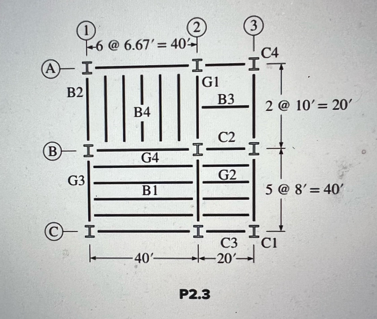

Transcribed Image Text:### Structural Grid Layout Diagram (P2.3)
#### Overview:
This diagram represents a structural grid layout commonly used in architectural and construction planning.
#### Elements Description:
1. **Columns**:
- The columns are indicated by circular markers labeled 1, 2, 3 vertically, and A, B, C horizontally.
- Each intersection of these labels (e.g., A-1, B-2, C-3) marks the position of a column.
2. **Beams**:
- Beams are denoted by alphanumeric labels such as B1, B2, B3, B4, G1, G2, G3, and G4.
- Vertical beams (e.g., B1, B2, B3, B4) run up and down between horizontal column lines.
- Horizontal beams (e.g., G1, G2, G3, G4) run left to right between vertical column lines.
#### Dimensions:
1. **Horizontal Dimensions**:
- The horizontal distance from point 1 to point 3 is segmented into six parts, each measuring 6.67 feet, therefore the total spans 40 feet.
- The first two sections from vertical line A to C span 20 feet each (3 segments of 8 feet for the total of 40 feet).
2. **Vertical Dimensions**:
- The vertical distance from line C4 to line C1 is segmented into five parts, each measuring 8 feet, therefore the total spans 40 feet.
- An additional vertical segment between C2 and C4 measures 2 sections at 10 feet each, thus totaling 20 feet.
#### Structural Grid Labeling:
- **Column Grid**:
- Row A: Points A-1, A-2, A-3
- Row B: Points B-1, B-2, B-3
- Row C: Points C-1, C-2, C-3
- **Beam Grid**:
- Between A and B: Beam B2, Beam G1
- Between B and C: Beam G3, Beam G4, Beam G2, Beam B3
- Additional Grid lines for segmentation: B1, B4.
#### Visual Representation:
- The diagram utilizes parallel lines to represent beams and solid lines with hash marking the segments of the grid. Columns are usually visualized as

Transcribed Image Text:### Building Section Diagram
**Description:**
The diagram illustrates a section of a building with specific measurements and labeled columns. The building section is depicted as a rectangular structure subdivided into smaller rectangular sections.
**Diagram Breakdown:**
1. **Overall Structure:**
- The diagram features a large rectangle divided into six smaller rectangles arranged in three rows and two columns.
2. **Columns:**
- There are two vertical columns labeled C1 and C3.
- Column C1 is positioned on the right side border of the building section.
- Column C3 is located in the middle.
3. **Measurements:**
- The total height of the building section is given as \(3 \times 12' = 36'\).
- The width of the building section is divided into two parts:
- The left section measures 40'.
- The right section measures 20'.
**Notations:**
- The height is noted as “3 @ 12' = 36’”, indicating that the height is divided into three sections, each 12 feet tall.
- The text "Building Section" is written below the diagram.
- The figure is labeled "P2.7" at the bottom center of the diagram.
This diagram is useful for visualizing and understanding architectural plans, allowing for precise identification of structural components and their dimensions.
Expert Solution
This question has been solved!
Explore an expertly crafted, step-by-step solution for a thorough understanding of key concepts.

This is a popular solution

Trending nowThis is a popular solution!

Step by stepSolved in 4 steps with 4 images

Knowledge Booster


Learn more about
Need a deep-dive on the concept behind this application? Look no further. Learn more about this topic, civil-engineering and related others by exploring similar questions and additional content below.Similar questions
- Please answer correctlyarrow_forwardA spiral column is 430 mm in diameter and is reinforced with 7-28 mm bars Grade 415. The spirals are 10 mm in diameter and concrete cover used is 40 mm. If f'c = 28 MPa, and the column has an unsupported length of 2.20 m, what is the safe ultimate load that the column can support using the 2001 NSCP specifications? Neglect moment in the column. Ku = 1.0arrow_forwardA concrete building has 12 stories, each story is 3.2 m high. The facade column has 400 kN axial load per floor and a cross sectional area of 300mm×700mm. Calculate the shortening of the column at the ground floor level and the sixth floor when using concrete f'c= 25 N/mm and 40 N/mm?. Explain if there will be any effect on the facade.arrow_forward
- The time effect factor for load combination 1.2D + 1.6(L, or S or R) + (L or 0.5W) is 0.9 O 0.8 O 0.6 O 0,7arrow_forward2. Using the tributary area method, compute the floor dead loads supported by columns A1 and B2 in Figure 1.2. The floor system consists of a 6-in.-thick reinforced concrete slab weighing 75 Ib/ft?. Allow 15 Ib/ft? for the weight of floor beams, utilities, and a ceiling suspended from the floor. The precast exterior wall supported by the perimeter beams weighs 600 lb/ft. 20 18 C.panel 9' 18 Epanel 10 10 11' ! 11 11'! 11 Epanel Epanel Epanel Figure 1.2arrow_forwardA floor slab 100 mm thick is cast monolithically with beams 250 mm wide 450 mm deep spaced 1.2 m on centers, on simple supports over a span of 5.0 m. The floor supports a service live load of 2.1 kPa. Using f.-21 MPa, rebar strength f, 415 MPa, calculate the following if a typical interior beam is reinforced with 3- 16-mm-dia. flexure bars at the bottom enclosed with 10-mm-dia. stirrups: 1. Nominal moment capacity (kN-m) of a typical interior beam in positive bending considering T-beam geometry. A. 96.66 C. 91.10 Maximum factored uniformly distributed load (kN/m) a typical interior B. 86.99 D. 81.99 2. beam can sustain against positive bending. В. 27.83 с. 26.23 D. 29.15 A. 30.93 3. Maximum service superimposed dead load in kPa. A. 17.73 C. 16.52 B. 11.08 D. 14.77arrow_forward
- A column in the upper story of a building is subjected to a compressive load from the followingsources: dead load = 30.8 kips, occupancy live load = 1.7 kips, roof live load = 18.7 kips, and snowload = 19.7 kips.a. If load and resistance factor design (LRFD) is used, determine the factored load (requiredstrength) to be used in the design of the column. Which ASCE load combination controls?b. What is the required design strength of the column?c. What is the required nominal strength of the column for a resistance factor phi of0.9?d. If allowable strength design (ASD), determine the required load capacity (requiredstrength) to be used in the design of the column. Which ASCE load combination controls.e. What is the required nominal strength of the column for a safety factor Omega of 1.67.arrow_forwardAnalysis/Design of Eccentrically Loaded Columns Using Interaction Diag. (35 pts-) Using the ACI column interaction graphs, select reinforcing for the short round spiral column shown in figure 2 iffc = 4000 psi, fy = 60,000 psi, Pu = 500 k, and Mu = 225 ft—k. In order to get fiJll credit print the interaction diagram(s) and clearlyr show your pg selection- Show your final results on a sketch.arrow_forward
arrow_back_ios
arrow_forward_ios
Recommended textbooks for you
 Structural Analysis (10th Edition)Civil EngineeringISBN:9780134610672Author:Russell C. HibbelerPublisher:PEARSON
 Principles of Foundation Engineering (MindTap Cou...Civil EngineeringISBN:9781337705028Author:Braja M. Das, Nagaratnam SivakuganPublisher:Cengage Learning
 Fundamentals of Structural AnalysisCivil EngineeringISBN:9780073398006Author:Kenneth M. Leet Emeritus, Chia-Ming Uang, Joel LanningPublisher:McGraw-Hill Education
 Traffic and Highway EngineeringCivil EngineeringISBN:9781305156241Author:Garber, Nicholas J.Publisher:Cengage Learning
Structural Analysis (10th Edition)
Civil Engineering
ISBN:9780134610672
Author:Russell C. Hibbeler
Publisher:PEARSON
Principles of Foundation Engineering (MindTap Cou...
Civil Engineering
ISBN:9781337705028
Author:Braja M. Das, Nagaratnam Sivakugan
Publisher:Cengage Learning
Fundamentals of Structural Analysis
Civil Engineering
ISBN:9780073398006
Author:Kenneth M. Leet Emeritus, Chia-Ming Uang, Joel Lanning
Publisher:McGraw-Hill Education
Traffic and Highway Engineering
Civil Engineering
ISBN:9781305156241
Author:Garber, Nicholas J.
Publisher:Cengage Learning