
Introductory Circuit Analysis (13th Edition)
13th Edition
ISBN: 9780133923605
Author: Robert L. Boylestad
Publisher: PEARSON
expand_more
expand_more
format_list_bulleted
Related questions
Concept explainers
Question
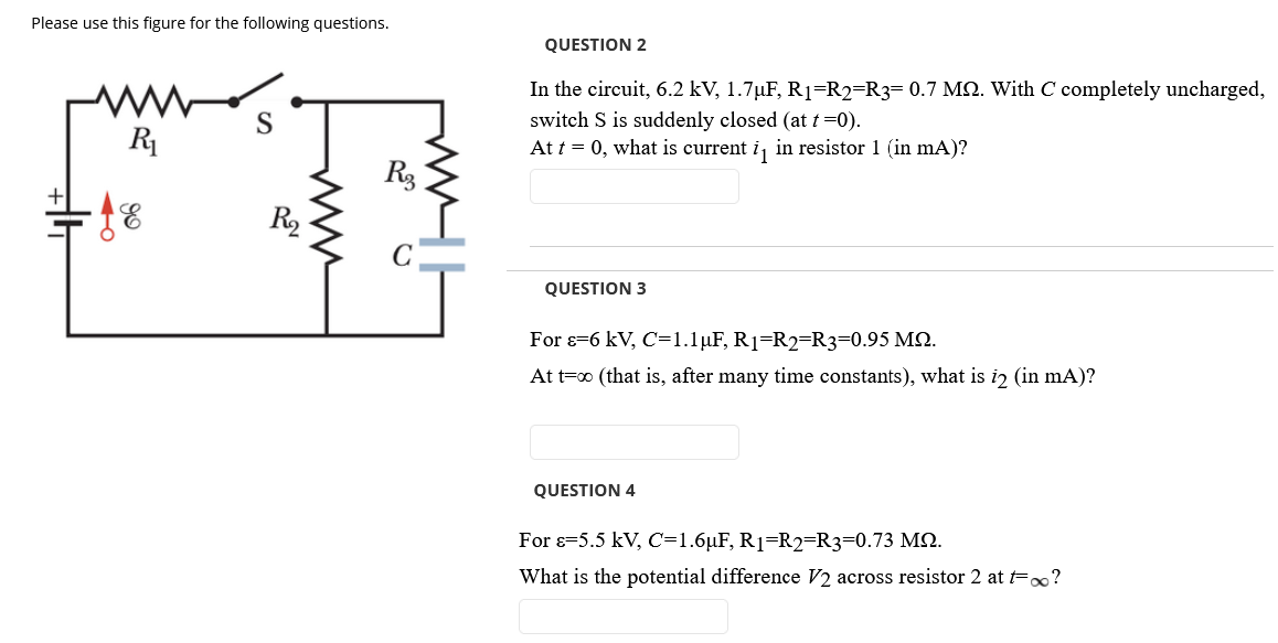

Transcribed Image Text:Please use this figure for the following questions.
QUESTION 2
In the circuit, 6.2 kV, 1.7µF, R1=R2=R3= 0.7 MN. With C completely uncharged,
switch S is suddenly closed (at t =0).
At t = 0, what is current i, in resistor 1 (in mA)?
S
R1
Rg
R2
QUESTION 3
For 8=6 kV, C=1.1µF, R1=R2=R3=0.95 M2.
At t=0 (that is, after many time constants), what is i2 (in mA)?
QUESTION 4
For s-5.5 kV, C=1.6µF, R1=R2=R3=0.73 M2.
What is the potential difference V2 across resistor 2 at t=o?
Expert Solution
This question has been solved!
Explore an expertly crafted, step-by-step solution for a thorough understanding of key concepts.

This is a popular solution

Trending nowThis is a popular solution!

Step by stepSolved in 2 steps

Knowledge Booster


Learn more about
Need a deep-dive on the concept behind this application? Look no further. Learn more about this topic, electrical-engineering and related others by exploring similar questions and additional content below.Similar questions
- Step by step what is the equivalent circuit for this diagramarrow_forwardQUESTION 8 Refer to the following phasor diagram. I2 4 I3 Which phasor is represented by /,? O 5.75 Z -90° A O 5.75 Z 90° A O 5.75 Z 180° A O 5.75 Z0°Aarrow_forwardThree capacitors 10 µF, 20 µF, 30 μF are connected in series across 150V (sinusoidal). Then identify the correct statement Maximum voltage will be applied across 10 µF Maximum voltage will be applied across 30 µF Maximum voltage will be applied across 20 µF Minimum voltage will be applied across 10 µFarrow_forward
- How many turns are required to produce 30 mH with a coil wound on a cylindrical coil having a cross-sectional area of 10 x 10-5 m² and a length of 0.05 m? The core has a permeability of 1.2 x 10⁻⁶? Express answer as a whole numberarrow_forward3-Determine the output voltage in Figure 8 for each of the following failure modes: (a) L1 open (b) L2 open (c) R1 open (d) a short across R2 5 V 1 MHz L₁ m 8.0 μΗ L₂ m 4.0 με Figure 8 R₁ ww 100 (2 R₂ 100 Ω R3 56 Ωarrow_forwardPlease Asaparrow_forward
arrow_back_ios
arrow_forward_ios
Recommended textbooks for you
- Introductory Circuit Analysis (13th Edition)Electrical EngineeringISBN:9780133923605Author:Robert L. BoylestadPublisher:PEARSON
 Delmar's Standard Textbook Of ElectricityElectrical EngineeringISBN:9781337900348Author:Stephen L. HermanPublisher:Cengage Learning
 Programmable Logic ControllersElectrical EngineeringISBN:9780073373843Author:Frank D. PetruzellaPublisher:McGraw-Hill Education
  Fundamentals of Electric CircuitsElectrical EngineeringISBN:9780078028229Author:Charles K Alexander, Matthew SadikuPublisher:McGraw-Hill Education
 Electric Circuits. (11th Edition)Electrical EngineeringISBN:9780134746968Author:James W. Nilsson, Susan RiedelPublisher:PEARSON
 Engineering ElectromagneticsElectrical EngineeringISBN:9780078028151Author:Hayt, William H. (william Hart), Jr, BUCK, John A.Publisher:Mcgraw-hill Education,
Introductory Circuit Analysis (13th Edition)
Electrical Engineering
ISBN:9780133923605
Author:Robert L. Boylestad
Publisher:PEARSON
Delmar's Standard Textbook Of Electricity
Electrical Engineering
ISBN:9781337900348
Author:Stephen L. Herman
Publisher:Cengage Learning
Programmable Logic Controllers
Electrical Engineering
ISBN:9780073373843
Author:Frank D. Petruzella
Publisher:McGraw-Hill Education
Fundamentals of Electric Circuits
Electrical Engineering
ISBN:9780078028229
Author:Charles K Alexander, Matthew Sadiku
Publisher:McGraw-Hill Education
Electric Circuits. (11th Edition)
Electrical Engineering
ISBN:9780134746968
Author:James W. Nilsson, Susan Riedel
Publisher:PEARSON
Engineering Electromagnetics
Electrical Engineering
ISBN:9780078028151
Author:Hayt, William H. (william Hart), Jr, BUCK, John A.
Publisher:Mcgraw-hill Education,