Introductory Circuit Analysis (13th Edition)
13th Edition
ISBN: 9780133923605
Author: Robert L. Boylestad
Publisher: PEARSON
expand_more
expand_more
format_list_bulleted
Concept explainers
Question
Please help solve the problems shown in the photo. Any help at all will be much appreciated! Picture 1 is the data, and Picture 2 has the problem statements. Thank you!

Transcribed Image Text:Design Objective: To design a filter whose output signal will exhibit a desired signal to noise
ratio.
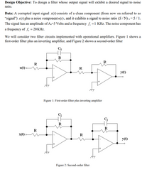
Data: A corrupted input signal x(t) consists of a clean component (from now on referred to as
"signal") s(t) plus a noise component 1(1), and it exhibits a signal to noise ratio (S / N) x = 5 / 1.
The signal has an amplitude of A.=5 Volts and a frequency f, =1 KHz. The noise component has
a frequency of f, = 20KHZ.
We will consider two filter circuits implemented with operational amplifiers. Figure 1 shows a
first-order filter plus an inverting amplifier, and Figure 2 shows a second-order filter
C1
R
R
R
x(t) •
R
y(t)
Figure 1: First-order filter plus inverting amplifier
C
R
R
R
x(t).
R
y(t)
Figure 2: Second-order filter

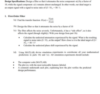
Transcribed Image Text:Design Specifications: Design a filter so that it attenuates the noise component n(t) by a factor of
10, while the signal component s(t) remains almost unchanged. In other words, our ideal target is
an output signal with a signal to noise ratio of (S / N) y = 50 / 1.
1. First-Order Filter
Y(@)
la) Find the transfer function H(@) =
X(@)
lb) Design the filter so that it attenuates the noise by a factor of 10
lc) The filter affects the noise severely. Unfortunately, it has a “side effect", as it also
affects the signal (though slightly). With your design from part lb):
Calculate the undesired attenuation experienced by the signal. What is the resulting
signal to noise ratio (S/N) y at the output? How close is it to the ideal target of (S/
N) y = 50 / 1?
Calculate the undesired phase shift experienced by the signal.
ld) Using MATLAB, devise simulation experiments to corroborate all your mathematical
predictions in parts 1b) and lc). All simulation experiments should include:
The computer code (MATLAB)
The plot (s), with the most noticeable features labeled.
A comment underneath each plot, explaining how the plot verifies the predicted
design performance.
Expert Solution
This question has been solved!
Explore an expertly crafted, step-by-step solution for a thorough understanding of key concepts.
This is a popular solution
Trending nowThis is a popular solution!
Step by stepSolved in 9 steps with 8 images

Knowledge Booster
Learn more about
Need a deep-dive on the concept behind this application? Look no further. Learn more about this topic, electrical-engineering and related others by exploring similar questions and additional content below.Similar questions
- Hello, I am doing some practice and I am getting hung up on my cross product derivation. I know it is supposed to be zero, but I want to prove it with the math. Could you help me out with this? Thank you for your time and effort, I appreciate the help. Please see attached for probelm.arrow_forwardWrite abstract & Itroduction for simple motion detector using 9v battery 555 timer sensor and alarm Abstarct What the project is? How we Built The circuit? How The circuit Can Be Built In Other ways Introduction- What is Motion Detectior What We tried to accomplish with that projectarrow_forwardPlease click on pic to open itarrow_forward
- Please answer in typing format please ASAP for the like Please answer in typing format please ASAP for the like please Please I will like it thanks please I will like itarrow_forwardtwwt tov + 202 VAB 2A Question #1: In less than three sentences, describe how you will solve this problem. A good answer can be as few as 6 or 7 words. wwwarrow_forward
arrow_back_ios
arrow_forward_ios
Recommended textbooks for you
 Introductory Circuit Analysis (13th Edition)Electrical EngineeringISBN:9780133923605Author:Robert L. BoylestadPublisher:PEARSON
 Delmar's Standard Textbook Of ElectricityElectrical EngineeringISBN:9781337900348Author:Stephen L. HermanPublisher:Cengage Learning
 Programmable Logic ControllersElectrical EngineeringISBN:9780073373843Author:Frank D. PetruzellaPublisher:McGraw-Hill Education
 Fundamentals of Electric CircuitsElectrical EngineeringISBN:9780078028229Author:Charles K Alexander, Matthew SadikuPublisher:McGraw-Hill Education
 Electric Circuits. (11th Edition)Electrical EngineeringISBN:9780134746968Author:James W. Nilsson, Susan RiedelPublisher:PEARSON
 Engineering ElectromagneticsElectrical EngineeringISBN:9780078028151Author:Hayt, William H. (william Hart), Jr, BUCK, John A.Publisher:Mcgraw-hill Education,

Introductory Circuit Analysis (13th Edition)
Electrical Engineering
ISBN:9780133923605
Author:Robert L. Boylestad
Publisher:PEARSON

Delmar's Standard Textbook Of Electricity
Electrical Engineering
ISBN:9781337900348
Author:Stephen L. Herman
Publisher:Cengage Learning

Programmable Logic Controllers
Electrical Engineering
ISBN:9780073373843
Author:Frank D. Petruzella
Publisher:McGraw-Hill Education

Fundamentals of Electric Circuits
Electrical Engineering
ISBN:9780078028229
Author:Charles K Alexander, Matthew Sadiku
Publisher:McGraw-Hill Education

Electric Circuits. (11th Edition)
Electrical Engineering
ISBN:9780134746968
Author:James W. Nilsson, Susan Riedel
Publisher:PEARSON

Engineering Electromagnetics
Electrical Engineering
ISBN:9780078028151
Author:Hayt, William H. (william Hart), Jr, BUCK, John A.
Publisher:Mcgraw-hill Education,