Elements Of Electromagnetics
7th Edition
ISBN: 9780190698614
Author: Sadiku, Matthew N. O.
Publisher: Oxford University Press
expand_more
expand_more
format_list_bulleted
Question
Please don't provide handwritten solution ....
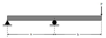
For the loading scenario in Figure , determine the maximum normal stress. Show the steps in this determination clearly using FBDs and equations

Transcribed Image Text:a
b-
P
Expert Solution
This question has been solved!
Explore an expertly crafted, step-by-step solution for a thorough understanding of key concepts.
Step by stepSolved in 3 steps with 12 images

Knowledge Booster
Learn more about
Need a deep-dive on the concept behind this application? Look no further. Learn more about this topic, mechanical-engineering and related others by exploring similar questions and additional content below.Similar questions
- Q6/ A material has a true stress -strain curve given by o=Kɛ", derive and calculate the true and engineering ultimate tensile strength of this material. (use : k=689.47kpa , n=0.5)arrow_forward1. A part made of Aluminum 6061-T6 has a yield strength = 400 MPa. For each stress state below, draw all 3 Mohr's circles, find the principal stresses, and calculate the safety factor against yield using both the distortion-energy (von Mises) and maximum shear stress (Tresca) criterions. (If relevant) A clearly labeled diagram (or diagrams) clearly pertaining to your analysis with a coordinate system and relevant labels. Final answer with appropriate units and significant figures. You can use the fprintf() command in MATLAB to format numerical results A 2-3 sentence reflection on your answer. Does it make sense? Why or why not? What are some implications?arrow_forwardPROBLEM SOLVING: A rigid bar is supported by three non-rigid steel rods, as shown. Rods AB and FG are 0.8 m long with a cross-sectional diameter of 30 mm. Rod CDE is made up of equally-long 0.40 – m CD and DE whose cross-sectional diameters are 60 mm and 30 mm, respectively. A 45 kN downward load is applied to the rigid bar. There is no initial strain before the application of the load. Let Esteel = 200 GPa Determine the internal forces on rods AB, CDE, and FG Determine the displacement of the rigid bar. If the allowable displacement of the horizontal rigid bar is 0.071 mm downwards, what maximum allowable vertical load can be applied for a factor of safety of 3? А F 0.40 m 60mm¢ D 0.8 m 0.8 m 30mm¢ 30mmф 0.40 m 30mm E G 45 kNarrow_forward
- Prarrow_forwardA thick-walled cylinder with closed ends has internal and external radii 100 mm and 180 mm respectively, is subject to internal and external pressures of 148 MPa and 58 MPa respectively. Apply Lame's equations to find the following: Radial and hoop stresses at radii 120 mm, 140 mm and 160 mm respectively. (a) (b) Axial stress of the cylinder.arrow_forwardFrom the graph find stress? and yong modulus,E?arrow_forward
- Please help. Please don't provide handwritten solution ...arrow_forwardFined the stress in each segment and the displacement in each segmentarrow_forwardThe stresses at a point on the surface of a generator shaft are o =-50 MPa, o, = 30 MPa and Try shown in Figure Q3. (Consider only the in-plane stresses. Note: the radius of the = -40 MPa as circle is given by R = ) + ()). Construct the Mohr's circle showing the centre of the circle as well as points A and B. (a) (b) Determine the principal stresses. (c) Show the principal stresses on a sketch of a properly oriented element. (d) Determine the maximum shear stresses. (e) Show the maximum shear stresses on a sketch of a properly oriented element. MPa B. A MPa MPaarrow_forward
- Answer D, E, Farrow_forwardIn the attached picture there is a sketch of a socket wrench. Assume the wrench is held at a fixed point “A”. The yield stress of the material is known to be 500 MPa. Answer the questions below Describe the stresses at point “A” and their causes and calculate the stresses. Determine the factor of safety against yield assuming the Tresca yield criteria. Determine the factor of safety against yield assuming the von Mises yield criteria using both principal stresses and “Cartesian” stresses. Do your values match or not, and is this expected? Explain. Do the calculated values make sense with the respect to the Tresca value? Explain, why or why not?arrow_forward
arrow_back_ios
arrow_forward_ios
Recommended textbooks for you
 Elements Of ElectromagneticsMechanical EngineeringISBN:9780190698614Author:Sadiku, Matthew N. O.Publisher:Oxford University Press
 Mechanics of Materials (10th Edition)Mechanical EngineeringISBN:9780134319650Author:Russell C. HibbelerPublisher:PEARSON
 Thermodynamics: An Engineering ApproachMechanical EngineeringISBN:9781259822674Author:Yunus A. Cengel Dr., Michael A. BolesPublisher:McGraw-Hill Education
 Control Systems EngineeringMechanical EngineeringISBN:9781118170519Author:Norman S. NisePublisher:WILEY
 Mechanics of Materials (MindTap Course List)Mechanical EngineeringISBN:9781337093347Author:Barry J. Goodno, James M. GerePublisher:Cengage Learning
 Engineering Mechanics: StaticsMechanical EngineeringISBN:9781118807330Author:James L. Meriam, L. G. Kraige, J. N. BoltonPublisher:WILEY

Elements Of Electromagnetics
Mechanical Engineering
ISBN:9780190698614
Author:Sadiku, Matthew N. O.
Publisher:Oxford University Press

Mechanics of Materials (10th Edition)
Mechanical Engineering
ISBN:9780134319650
Author:Russell C. Hibbeler
Publisher:PEARSON

Thermodynamics: An Engineering Approach
Mechanical Engineering
ISBN:9781259822674
Author:Yunus A. Cengel Dr., Michael A. Boles
Publisher:McGraw-Hill Education

Control Systems Engineering
Mechanical Engineering
ISBN:9781118170519
Author:Norman S. Nise
Publisher:WILEY

Mechanics of Materials (MindTap Course List)
Mechanical Engineering
ISBN:9781337093347
Author:Barry J. Goodno, James M. Gere
Publisher:Cengage Learning

Engineering Mechanics: Statics
Mechanical Engineering
ISBN:9781118807330
Author:James L. Meriam, L. G. Kraige, J. N. Bolton
Publisher:WILEY