
Structural Analysis
6th Edition
ISBN: 9781337630931
Author: KASSIMALI, Aslam.
Publisher: Cengage,
expand_more
expand_more
format_list_bulleted
Related questions
Question
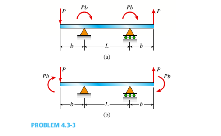
Determine the shear force V and bending moment M at the midpoint of the beam with overhangs (see figure). Note that one load acts downward and the other upward, and clockwise moments Pb are applied at each support. Repeat if moments Ph are moved to the ends of the beam (Fig, b).

Transcribed Image Text:Pb
Pb
-L
(a)
Pb
Pb
(b)
PROBLEM 4.3-3
Expert Solution
This question has been solved!
Explore an expertly crafted, step-by-step solution for a thorough understanding of key concepts.

This is a popular solution

Trending nowThis is a popular solution!

Step by stepSolved in 3 steps with 4 images

Knowledge Booster


Learn more about
Need a deep-dive on the concept behind this application? Look no further. Learn more about this topic, civil-engineering and related others by exploring similar questions and additional content below.Similar questions
- Problem 2 Determine the support reactions of the beam loaded as shown below then draw the shear and bending moment diagrams. P=9K 31 * 12'arrow_forwardFor the indeterminate frames shown, determine the support reactions using force method. El constant. 1. 3k/ft B 20 ft 15ftarrow_forwardPROBLEM 1: The beam shown below has a fixed support at A and a roller at B. El is constant. Use the FORCE METHOD to: a. Find all reactions (clearly show the value and direction of each reaction at each support) b. Draw the Shear (V) and Moment (M) diagrams (clearly show the peak values, signs, and location) 4 kip/ft A 8 ft B *arrow_forward
- 4kN 4 kN Analyze the bęam as shown 35KN 4kN 3.5 3.5 3.5 2 kN- m 3kN. m 2m 2m 2m 2m 2m 2m 2 simplify the forces and moments. draw the free body diagram. determine the support reactions. draw shear and moment diagram. find the maximum and minimum shear and moment. determine the moment at point X.arrow_forward4.5.24 Beams ABC and CD are supported at A, C, and D, and joined by a hinge (or moment relief) just to the left of C. The support at A is sliding (hence the reaction at Ay = 0 for the load shown in the figure). Determine the support reactions, then draw shear (V) and moment (M) diagrams. Identify all critical values V and M, and also the distance to where V and / or M are zero.arrow_forward
arrow_back_ios
arrow_forward_ios
Recommended textbooks for you
 Structural Analysis (10th Edition)Civil EngineeringISBN:9780134610672Author:Russell C. HibbelerPublisher:PEARSON
 Principles of Foundation Engineering (MindTap Cou...Civil EngineeringISBN:9781337705028Author:Braja M. Das, Nagaratnam SivakuganPublisher:Cengage Learning
 Fundamentals of Structural AnalysisCivil EngineeringISBN:9780073398006Author:Kenneth M. Leet Emeritus, Chia-Ming Uang, Joel LanningPublisher:McGraw-Hill Education
 Traffic and Highway EngineeringCivil EngineeringISBN:9781305156241Author:Garber, Nicholas J.Publisher:Cengage Learning
Structural Analysis (10th Edition)
Civil Engineering
ISBN:9780134610672
Author:Russell C. Hibbeler
Publisher:PEARSON
Principles of Foundation Engineering (MindTap Cou...
Civil Engineering
ISBN:9781337705028
Author:Braja M. Das, Nagaratnam Sivakugan
Publisher:Cengage Learning
Fundamentals of Structural Analysis
Civil Engineering
ISBN:9780073398006
Author:Kenneth M. Leet Emeritus, Chia-Ming Uang, Joel Lanning
Publisher:McGraw-Hill Education
Traffic and Highway Engineering
Civil Engineering
ISBN:9781305156241
Author:Garber, Nicholas J.
Publisher:Cengage Learning