
Structural Analysis
6th Edition
ISBN: 9781337630931
Author: KASSIMALI, Aslam.
Publisher: Cengage,
expand_more
expand_more
format_list_bulleted
Related questions
Question
part 4 and 5 please
![**Part 4**
Calculate the moment of inertia for the entire cross-section about its z centroidal axis.
- **Answer:**
\( I_z = \) [Input Field] in\(^4\)
[Button: eTextbook and Media]
[Button: Save for Later]
[Button: Submit Answer]
---
**Part 5**
Enter the maximum positive and negative bending moments for the beam. One method for determining these would be to begin by drawing shear-force and bending-moment diagrams for the beam on a piece of paper. Be sure to use the sign conventions from Section 7.1. Determine the maximum positive and negative bending moments from your bending-moment diagram. The "maximum negative bending moment" is the negative bending moment with the largest magnitude. Enter the maximum negative moment as a negative value here.
- **Answers:**
- \( M_{\text{max}+} = \) [Input Field] lb-ft
- \( M_{\text{max}-} = \) [Input Field] lb-ft
Note: There are no graphs or diagrams included in the image.](https://content.bartleby.com/qna-images/question/99e37c92-095a-4cae-adf6-01aeaaa5668c/54c3f178-580b-4941-9c9a-aa4c3d9bfd58/nwhsqnx_processed.png)

Transcribed Image Text:**Part 4**
Calculate the moment of inertia for the entire cross-section about its z centroidal axis.
- **Answer:**
\( I_z = \) [Input Field] in\(^4\)
[Button: eTextbook and Media]
[Button: Save for Later]
[Button: Submit Answer]
---
**Part 5**
Enter the maximum positive and negative bending moments for the beam. One method for determining these would be to begin by drawing shear-force and bending-moment diagrams for the beam on a piece of paper. Be sure to use the sign conventions from Section 7.1. Determine the maximum positive and negative bending moments from your bending-moment diagram. The "maximum negative bending moment" is the negative bending moment with the largest magnitude. Enter the maximum negative moment as a negative value here.
- **Answers:**
- \( M_{\text{max}+} = \) [Input Field] lb-ft
- \( M_{\text{max}-} = \) [Input Field] lb-ft
Note: There are no graphs or diagrams included in the image.

Transcribed Image Text:### Beam Analysis for Engineering Education
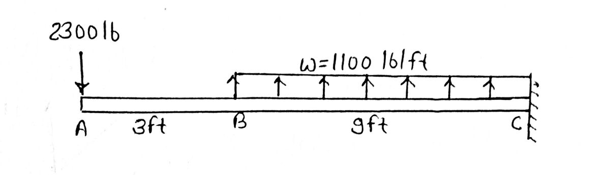
A channel shape is used to support the loads shown on the beam. The dimensions of the shape are also shown. Assume:
- \( L_{AB} = 3 \) ft,
- \( L_{BC} = 9 \) ft,
- \( P = 2300 \) lb,
- \( w = 1100 \) lb/ft,
- \( b = 16 \) in.,
- \( d = 10 \) in.,
- \( t = 0.500 \) in.
Consider the entire 12-ft length of the beam and determine:
- (a) the maximum tension bending stress at any location along the beam, and
- (b) the maximum compression bending stress at any location along the beam.
#### Diagram and Description
**Diagram Components:**
1. **Beam Diagram:**
- A horizontal beam is shown resting on supports at points A and C.
- A downward point load \( P \) is applied at the leftmost end, and a uniform distributed load \( w \) acts across the distance leading to point C.
- \( L_{AB} \) is the distance between points A and B, and \( L_{BC} \) is the distance between points B and C.
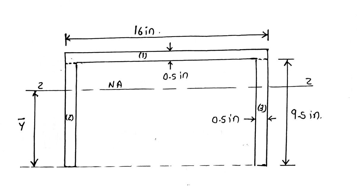
2. **Cross-Sectional View:**
- Displays the shape of the channel used for the beam.
- Labeled dimensions include:
- Width (\( b \)) of the channel.
- Height (\( d \)) of the vertical stems of the channel.
- Thickness (\( t \)) of the channel material.
#### Cross-Sectional Area Analysis
The cross-sectional area is divided into three parts:
1. **Top Horizontal Flange:**
- Rectangular cross-section: \( 16 \) in. x \( 0.500 \) in.
2. **Left Vertical Stem:**
- Rectangular cross-section: \( 0.500 \) in. x \( 9.5 \) in.
3. **Right Vertical Stem:**
- Rectangular cross-section: \( 0.500 \) in. x \( 9.5 \) in.
#### Centroid Calculation Instructions
To find the areas and the centroid locations in the y-direction for each part, follow these steps:
- Enter the centroid locations, \( y_1, y_2, \) and \(
Expert Solution
arrow_forward
Step 1: State the given data
Determine
a. Maximum positive and negative bending moment.
b. Moment of inertia about centroid Z-axis.
c. Maximum tensile and compressive stress.

Step by stepSolved in 10 steps with 13 images

Knowledge Booster


Learn more about
Need a deep-dive on the concept behind this application? Look no further. Learn more about this topic, civil-engineering and related others by exploring similar questions and additional content below.Similar questions
- What is the Moody Diagram used for? Edit View Insert Format Tools Table 12pt Paragraph B IU Αν VT² Varrow_forwardWhere would the elevation noted below be found in a set of architectural drawings? ROOM R-1 ELEVATION 6 A3.01 SCALE: 1/4-1-0 Sheet 6, Section A3.01 Sheet A3.01, Section 6 Sheet A3, Section 01 Sheet 1, Section A3arrow_forward
Recommended textbooks for you
 Structural Analysis (10th Edition)Civil EngineeringISBN:9780134610672Author:Russell C. HibbelerPublisher:PEARSON
 Principles of Foundation Engineering (MindTap Cou...Civil EngineeringISBN:9781337705028Author:Braja M. Das, Nagaratnam SivakuganPublisher:Cengage Learning
 Fundamentals of Structural AnalysisCivil EngineeringISBN:9780073398006Author:Kenneth M. Leet Emeritus, Chia-Ming Uang, Joel LanningPublisher:McGraw-Hill Education
 Traffic and Highway EngineeringCivil EngineeringISBN:9781305156241Author:Garber, Nicholas J.Publisher:Cengage Learning
Structural Analysis (10th Edition)
Civil Engineering
ISBN:9780134610672
Author:Russell C. Hibbeler
Publisher:PEARSON
Principles of Foundation Engineering (MindTap Cou...
Civil Engineering
ISBN:9781337705028
Author:Braja M. Das, Nagaratnam Sivakugan
Publisher:Cengage Learning
Fundamentals of Structural Analysis
Civil Engineering
ISBN:9780073398006
Author:Kenneth M. Leet Emeritus, Chia-Ming Uang, Joel Lanning
Publisher:McGraw-Hill Education
Traffic and Highway Engineering
Civil Engineering
ISBN:9781305156241
Author:Garber, Nicholas J.
Publisher:Cengage Learning