Elements Of Electromagnetics
7th Edition
ISBN: 9780190698614
Author: Sadiku, Matthew N. O.
Publisher: Oxford University Press
expand_more
expand_more
format_list_bulleted
Concept explainers
Question
I downloaded this question multiple times but I had no answer.
I need (d and e)

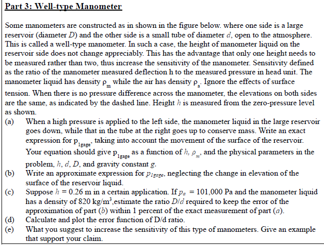
Transcribed Image Text:Part 3: Well-type Manometer
Some manometers are constructed as in shown in the figure below. where one side is a large
reservoir (diameter D) and the other side is a small tube of diameter d, open to the atmosphere.
This is called a well-type manometer. In such a case, the height of manometer liquid on the
reservoir side does not change appreciably. This has the advantage that only one height needs to
be measured rather than two, thus increase the sensitivity of the manometer. Sensitivity defined
as the ratio of the manometer measured deflection h to the measured pressure in head unit. The
manometer liquid has density p while the air has density p, Ignore the effects of surface
tension. When there is no pressure difference across the manometer, the elevations on both sides
are the same, as indicated by the dashed line. Height h is measured from the zero-pressure level
as shown.
(a) When a high pressure is applied to the left side, the manometer liquid in the large reservoir
goes down, while that in the tube at the right goes up to conserve mass. Write an exact
expression for p taking into account the movement of the surface of the reservoir.
Your equation should give proze as a function of h, p and the physical parameters in the
problem, h, d, D, and gravity constant g.
(b) Write an approximate expression for pigage, neglecting the change in elevation of the
surface of the reservoir liquid.
(c) Suppose h = 0.26 m in a certain application. If pa = 101,000 Pa and the manometer liquid
has a density of 820 kg/m²,estimate the ratio Dld required to keep the error of the
approximation of part (b) within 1 percent of the exact measurement of part (a).
|(d) Calculate and plot the error function of D/d ratio.
(e)
Igage
What you suggest to increase the sensitivity of this type of manometers. Give an example
that support your claim.

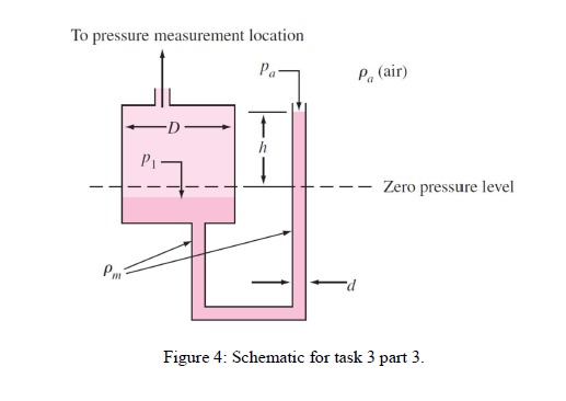
Transcribed Image Text:To pressure measurement location
Pa-
Pa (air)
Zero pressure level
Pm
P-
Figure 4: Schematic for task 3 part 3.
Expert Solution
This question has been solved!
Explore an expertly crafted, step-by-step solution for a thorough understanding of key concepts.
Step by stepSolved in 2 steps with 7 images

Knowledge Booster
Learn more about
Need a deep-dive on the concept behind this application? Look no further. Learn more about this topic, mechanical-engineering and related others by exploring similar questions and additional content below.Similar questions
- Q2/ Are the adverbs of frequency in the correct () or incorrect (X) places? Correct the wrong sentences. 1- She has always liked Peter. 2- Never I have anything to eat in the morning. 3- He sometimes takes his daughter to school. 4- She goes usually abroad on business. 5- He has never enough money. 6- We rarely have tests in class. 7- My teacher gives us often too much homework. 8- Ahmed usually is late for class.arrow_forwardPlease answer question and just send me the paper solutions asap dont type the answer question 2abc asaparrow_forwardEngr 215 Matlab Fahrenheit to Celsius using multiple statements Given a Fahrenheit value temperatureFahrenheit, write a statement that assigns temperatureCelsius with the equivalent Celsius value. While the equation is C = 5/9 * (F - 32), as an exercise use two statements, the first of which is "fractionalMultiplier = 5/9;"]arrow_forward
- Problem 1: (5 points) ements Decoding a Message The cryptogram below was encoded with a 2 x 2 matrix. The last word of the utton message is_RON. What is the message? 8 21 -15 - 10 -13 –13 5 10 5 25 5 19 –1 6 20 40 - 18 – 18 1 16 ents ns Problem 2: (15 points) Wildlife A wildlife management team studied the reproduction rates of deer in three tracts of a wildlife preserve. The team recorded the number of females x in each tract and the percent of females y in each tract that had offspring the following year. The table shows the results. nila Library esentation MS ory Survey Number, x 100 120 140 UDENTS 19 Percent, y 75 68 55 ATION al Faculty (a) Find the least squares regression line for the data. ance on Part ear from (b) Use a graphing utility to graph the model and the data in the same viewing window. How your Handled Classes (c) Use the model to create a table of estimated values for y. Compare the estimated values with the actual data. (d) Use the model to estimate the percent of…arrow_forward⦁ “God himself could not sink this ship” This is an advertisement for the Titanic, produced in the early 1900s. However, after colliding with an iceberg at dawn on April 15, 1912, two rivers were formed, and out of the 2,200 people on board, 1,500 people, including the captain, sank with the ship. According to a later investigation, the “temperature change theory” (DBTT theory) was the most promising cause of the sinking. Give a brief guess of the cause of the ship's sinking in relation to temperature.arrow_forwardQI: A/ Put true or false in the following sentences. 1-The state of equilibrium is applied to bodies unstable or at a constant speed. 2-Force is the act that changes or attempts to change the body's kinetic state, shape, or size. 3 - The principle of the transferability of force states that it is a force external effect On an body depends on its effect point as long as this point falls on the same effect line. 4-Moment is the ability to rotate the body that affects it around the parallel axis at the plane containing the force and its arm. 5-Liquids friction occurs when layers of liquid flow at a different speed. B/ -Calculate the moment of the 90-N force about point O for the condition e=10arrow_forward
- Option: -SC plane 110 -SC plane 100 -FCC plane 111 -SC plane 111 -FCC plane 110 -BCC plane 100 -BCC plane 111 -FCC plane 100 -None of the provided choices -BCC plane 110 could you please tell me how to get the answerarrow_forwardi li. In. N O 9:00 docs.google.com ô8 ( marks Tu) Work -------- ( around , still , together) إجابتك (project , money , in bank account) Invest --- إجابتك Go -( an accident , first in a race, abroad ) إجابتك Make -------( reservation , sure , some shopping ) إجابتك II IIarrow_forwardHello Sir,Good Morning I have a question in my home work related mechatronics lesson. The following below is my question. Please advise thank you.arrow_forward
- Build the pneumatic circuit in the following pneumatic sequence using the cascade method: [A+ B+] [A- B- C+ A+] [B+ A- B- C-]arrow_forwardE O ".ll Asiacell :D docs.google.com/forms Q1: Complete the pairs of sentences with the verb in brackets. Use the present simple for one and the .present continuous for the other إجابتك |-- (think) -1 of your problem. I (think) there's good solution إجابتك - (see) -2 you- What I mean? What time- you * ?(see) the film إجابتكarrow_forwardBuild the pneumatic circuit in the following pneumatic sequence using the cascade method: [A- B-] [C+ D- A+] [C- B+ D+]arrow_forward
arrow_back_ios
SEE MORE QUESTIONS
arrow_forward_ios
Recommended textbooks for you
 Elements Of ElectromagneticsMechanical EngineeringISBN:9780190698614Author:Sadiku, Matthew N. O.Publisher:Oxford University Press
 Mechanics of Materials (10th Edition)Mechanical EngineeringISBN:9780134319650Author:Russell C. HibbelerPublisher:PEARSON
 Thermodynamics: An Engineering ApproachMechanical EngineeringISBN:9781259822674Author:Yunus A. Cengel Dr., Michael A. BolesPublisher:McGraw-Hill Education
 Control Systems EngineeringMechanical EngineeringISBN:9781118170519Author:Norman S. NisePublisher:WILEY
 Mechanics of Materials (MindTap Course List)Mechanical EngineeringISBN:9781337093347Author:Barry J. Goodno, James M. GerePublisher:Cengage Learning
 Engineering Mechanics: StaticsMechanical EngineeringISBN:9781118807330Author:James L. Meriam, L. G. Kraige, J. N. BoltonPublisher:WILEY

Elements Of Electromagnetics
Mechanical Engineering
ISBN:9780190698614
Author:Sadiku, Matthew N. O.
Publisher:Oxford University Press

Mechanics of Materials (10th Edition)
Mechanical Engineering
ISBN:9780134319650
Author:Russell C. Hibbeler
Publisher:PEARSON

Thermodynamics: An Engineering Approach
Mechanical Engineering
ISBN:9781259822674
Author:Yunus A. Cengel Dr., Michael A. Boles
Publisher:McGraw-Hill Education

Control Systems Engineering
Mechanical Engineering
ISBN:9781118170519
Author:Norman S. Nise
Publisher:WILEY

Mechanics of Materials (MindTap Course List)
Mechanical Engineering
ISBN:9781337093347
Author:Barry J. Goodno, James M. Gere
Publisher:Cengage Learning

Engineering Mechanics: Statics
Mechanical Engineering
ISBN:9781118807330
Author:James L. Meriam, L. G. Kraige, J. N. Bolton
Publisher:WILEY