
Introductory Circuit Analysis (13th Edition)
13th Edition
ISBN: 9780133923605
Author: Robert L. Boylestad
Publisher: PEARSON
expand_more
expand_more
format_list_bulleted
Related questions
Question
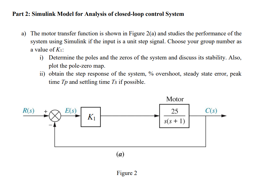

Transcribed Image Text:Part 2: Simulink Model for Analysis of closed-loop control System
a) The motor transfer function is shown in Figure 2(a) and studies the performance of the
system using Simulink if the input is a unit step signal. Choose your group number as
a value of K₁:
i)
R(s)
Determine the poles and the zeros of the system and discuss its stability. Also,
plot the pole-zero map.
ii) obtain the step response of the system, % overshoot, steady state error, peak
time Tp and settling time Ts if possible.
E(s)
K₁
(a)
Figure 2
Motor
25
s(s+1)
C(s)
Expert Solution
This question has been solved!
Explore an expertly crafted, step-by-step solution for a thorough understanding of key concepts.

Step by stepSolved in 3 steps with 3 images

Knowledge Booster


Learn more about
Need a deep-dive on the concept behind this application? Look no further. Learn more about this topic, electrical-engineering and related others by exploring similar questions and additional content below.Similar questions
- Control system, can you explain two differences between feedfoward and feedback for this figure ?arrow_forwardNeed help only with parts D and E and no matlab help required, just computationarrow_forwardQUESTION 3 Consider a unity negative feedback control system. Assume that the plant G(s) does not have an integrator and you are using a proportional compensator K. You want to increase the closed-loop step tracking performance. Currently, the steady- state tracking error of the closed-loop system with K=K_old to a unit step signal is 0.1. You would like this error to be reduced to 0.02 with a new proportional compensator K=K_new. How does the proportional gain have to change to make this possible? We assume that the closed-loop is stable for all values of the proportional gain. Do not guess as incorrect answers will incur a penalty. K_new = 6.33 K_old K_new = 5.44 K_old K_new = 5 K_old K_new = 4.66 K_oldarrow_forward
- Solve B part only plz in 30 min pleasearrow_forwardI need help on this asap:arrow_forwardDesign a closed loop speed control system so that a separately excited DC motor can be controlledwith a DC chopper. Provide the principle diagram of the system in block diagrams with thenecessary control signals and feedback paths.arrow_forward
arrow_back_ios
arrow_forward_ios
Recommended textbooks for you
- Introductory Circuit Analysis (13th Edition)Electrical EngineeringISBN:9780133923605Author:Robert L. BoylestadPublisher:PEARSON
 Delmar's Standard Textbook Of ElectricityElectrical EngineeringISBN:9781337900348Author:Stephen L. HermanPublisher:Cengage Learning
 Programmable Logic ControllersElectrical EngineeringISBN:9780073373843Author:Frank D. PetruzellaPublisher:McGraw-Hill Education
  Fundamentals of Electric CircuitsElectrical EngineeringISBN:9780078028229Author:Charles K Alexander, Matthew SadikuPublisher:McGraw-Hill Education
 Electric Circuits. (11th Edition)Electrical EngineeringISBN:9780134746968Author:James W. Nilsson, Susan RiedelPublisher:PEARSON
 Engineering ElectromagneticsElectrical EngineeringISBN:9780078028151Author:Hayt, William H. (william Hart), Jr, BUCK, John A.Publisher:Mcgraw-hill Education,
Introductory Circuit Analysis (13th Edition)
Electrical Engineering
ISBN:9780133923605
Author:Robert L. Boylestad
Publisher:PEARSON
Delmar's Standard Textbook Of Electricity
Electrical Engineering
ISBN:9781337900348
Author:Stephen L. Herman
Publisher:Cengage Learning
Programmable Logic Controllers
Electrical Engineering
ISBN:9780073373843
Author:Frank D. Petruzella
Publisher:McGraw-Hill Education
Fundamentals of Electric Circuits
Electrical Engineering
ISBN:9780078028229
Author:Charles K Alexander, Matthew Sadiku
Publisher:McGraw-Hill Education
Electric Circuits. (11th Edition)
Electrical Engineering
ISBN:9780134746968
Author:James W. Nilsson, Susan Riedel
Publisher:PEARSON
Engineering Electromagnetics
Electrical Engineering
ISBN:9780078028151
Author:Hayt, William H. (william Hart), Jr, BUCK, John A.
Publisher:Mcgraw-hill Education,