
Structural Analysis
6th Edition
ISBN: 9781337630931
Author: KASSIMALI, Aslam.
Publisher: Cengage,
expand_more
expand_more
format_list_bulleted
Related questions
Question
Subject reinforced concrete design please solve part C and D
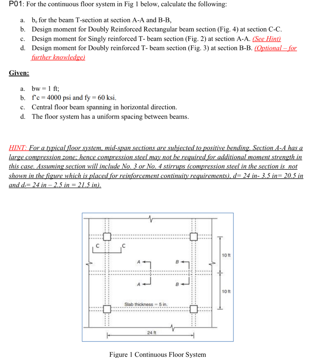

Transcribed Image Text:P01: For the continuous floor system in Fig 1 below, calculate the following:
a. be for the beam T-section at section A-A and B-B,
b. Design moment for Doubly Reinforced Rectangular beam section (Fig. 4) at section C-C.
c. Design moment for Singly reinforced T- beam section (Fig. 2) at section A-A. (See Hint)
d. Design moment for Doubly reinforced T- beam section (Fig. 3) at section B-B. (Optional - for
further knowledge)
Given:
a.
bw = 1 ft;
b.
f'c = 4000 psi and fy = 60 ksi.
c. Central floor beam spanning in horizontal direction.
d. The floor system has a uniform spacing between beams.
HINT: For a typical floor system, mid-span sections are subjected to positive bending. Section A-A has a
large compression zone; hence compression steel may not be required for additional moment strength in
this case. Assuming section will include No. 3 or No. 4 stirrups (compression steel in the section is not
shown in the figure which is placed for reinforcement continuity requirements), d= 24 in- 3.5 in= 20.5 in
and d= 24 in - 2.5 in = 21.5 in).
7
Slab thickness= 5 in.
24 ft
Figure 1 Continuous Floor System
10 ft
10 ft

Transcribed Image Text:3 No. 5 bars
be= 72 in.
6 No. 7 bars
12 in.
I 3.5 in.
Figure 2 T-Beam section at A-A section
13 No. 8 bars
2 No. 8 (No. 25)
b₂ = 72 in.
6 No. 10 (No. 32)
3 No. 7 bars
12 in.
I = 2.5 in.
Is
5. in.
12"
Figure 3 T-Beam Section at B-B section
2/2
-2.5 in.
3 No. 5 bars
24"
Figure 4 Rectangular Beam Section at C-C
24 in.
5 in.
24 in.
Expert Solution
This question has been solved!
Explore an expertly crafted, step-by-step solution for a thorough understanding of key concepts.

This is a popular solution

Trending nowThis is a popular solution!

Step by stepSolved in 8 steps with 21 images

Knowledge Booster


Learn more about
Need a deep-dive on the concept behind this application? Look no further. Learn more about this topic, civil-engineering and related others by exploring similar questions and additional content below.Similar questions
- Where should the primary longitudinal reinforcement be placed in a cantilever beam? Near the top of the beam In the middle of the beam Near the bottom of the beam Both near the top and near the bottomarrow_forwardRefer to the diagram of precast concrete building below and answer the following questions. What type of precast concrete element directly supports this building's floors? Precast walls Precast "T" beams Precast "L" girders Precast Columnsarrow_forward
Recommended textbooks for you
 Structural Analysis (10th Edition)Civil EngineeringISBN:9780134610672Author:Russell C. HibbelerPublisher:PEARSON
 Principles of Foundation Engineering (MindTap Cou...Civil EngineeringISBN:9781337705028Author:Braja M. Das, Nagaratnam SivakuganPublisher:Cengage Learning
 Fundamentals of Structural AnalysisCivil EngineeringISBN:9780073398006Author:Kenneth M. Leet Emeritus, Chia-Ming Uang, Joel LanningPublisher:McGraw-Hill Education
 Traffic and Highway EngineeringCivil EngineeringISBN:9781305156241Author:Garber, Nicholas J.Publisher:Cengage Learning
Structural Analysis (10th Edition)
Civil Engineering
ISBN:9780134610672
Author:Russell C. Hibbeler
Publisher:PEARSON
Principles of Foundation Engineering (MindTap Cou...
Civil Engineering
ISBN:9781337705028
Author:Braja M. Das, Nagaratnam Sivakugan
Publisher:Cengage Learning
Fundamentals of Structural Analysis
Civil Engineering
ISBN:9780073398006
Author:Kenneth M. Leet Emeritus, Chia-Ming Uang, Joel Lanning
Publisher:McGraw-Hill Education
Traffic and Highway Engineering
Civil Engineering
ISBN:9781305156241
Author:Garber, Nicholas J.
Publisher:Cengage Learning