
Introductory Circuit Analysis (13th Edition)
13th Edition
ISBN: 9780133923605
Author: Robert L. Boylestad
Publisher: PEARSON
expand_more
expand_more
format_list_bulleted
Related questions
Concept explainers
Question

Transcribed Image Text:**Circuit Analysis Problem**
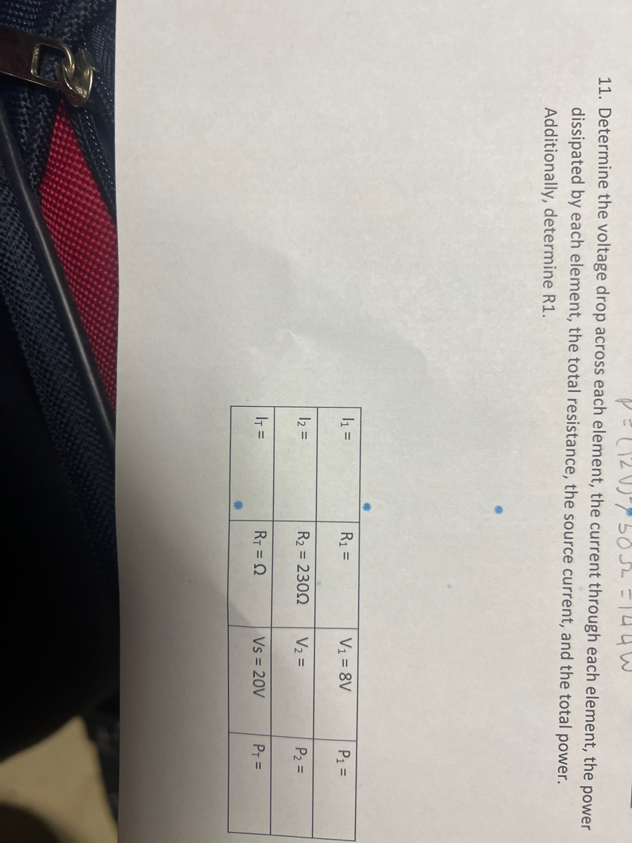
11. Determine the voltage drop across each element, the current through each element, the power dissipated by each element, the total resistance, the source current, and the total power. Additionally, determine R1.
**Table: Circuit Parameters**
| | | | | |
|---|---|---|----|----|
| I₂ = | I₂ = | I₁ = | I₁ = |
| R₂ = | R₂ = 230Ω | R₁ = | R₁ = |
| Rₜ = Ω | | V₂ = | V₁ = 8V |
| Vs = 20V | | | |
| Pₜ = | P₂ = | P₁ = | |
**Instructions**
Given that R₂ = 230Ω and V₁ = 8V, you need to compute:
- Voltage drop across each element (V₁, V₂)
- Current through each element (I₁, I₂)
- Power dissipated by each element (P₁, P₂)
- Total resistance (Rₜ)
- Source current
- Total power (Pₜ)
- Resistance R₁
Use the basic formulas from Ohm's Law and power calculations for these computations.
![**Circuit Power Calculation Problem**
**Task**: Calculate the power in each of the three circuits shown below.
**Diagram Explanation**:
This is a simple electrical circuit with the following components:
- A 20V battery.
- Two resistors in series:
- Resistor R2 with a resistance of 230Ω.
- Resistor R1 (resistance not specified in the diagram).
**Instructions**:
1. Analyze the circuit to determine the total resistance.
2. Use Ohm’s Law to find the current flowing through the circuit.
3. Calculate the power dissipated by each resistor using the formula:
\[ P = I^2 \times R \]
where \( P \) is power, \( I \) is current, and \( R \) is resistance.](https://content.bartleby.com/qna-images/question/8a2e9018-6ef7-49be-821f-0ff43f4b9b5d/ee5bdcb1-6441-49b0-9d04-4ed78fa23a15/b45md1_processed.jpeg)
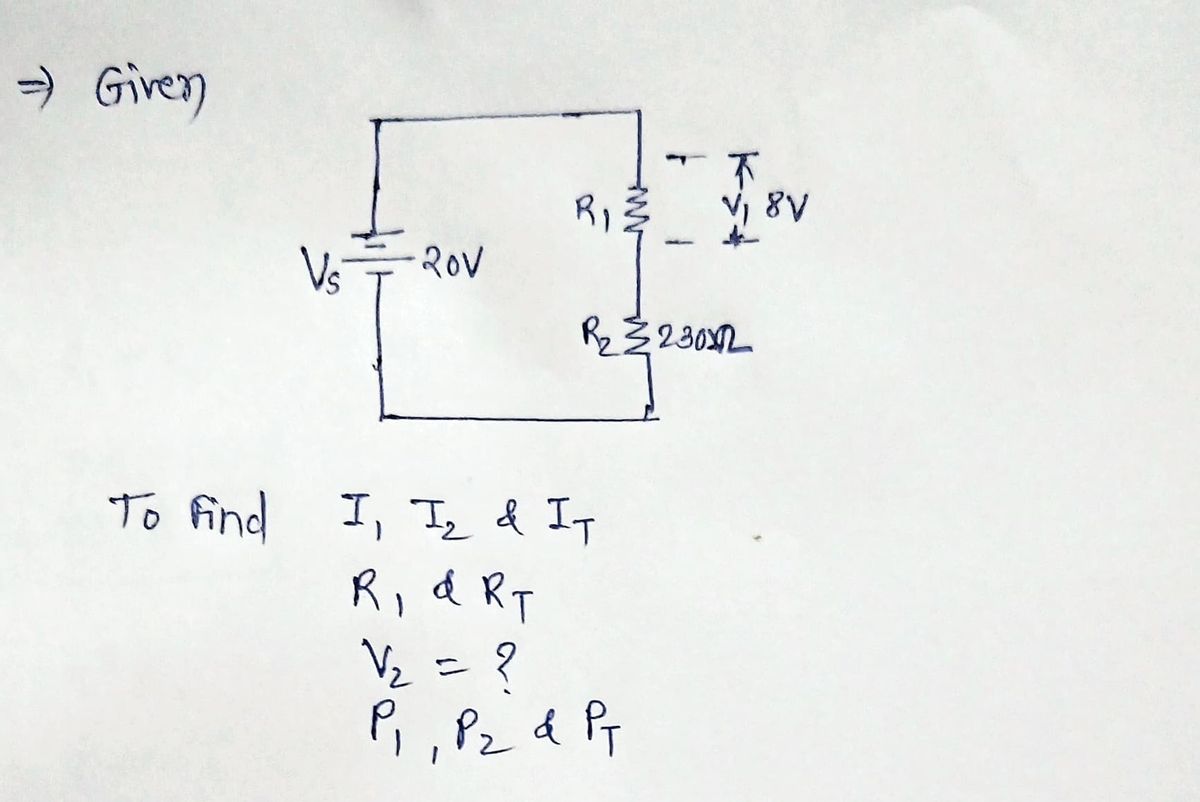
Transcribed Image Text:**Circuit Power Calculation Problem**
**Task**: Calculate the power in each of the three circuits shown below.
**Diagram Explanation**:
This is a simple electrical circuit with the following components:
- A 20V battery.
- Two resistors in series:
- Resistor R2 with a resistance of 230Ω.
- Resistor R1 (resistance not specified in the diagram).
**Instructions**:
1. Analyze the circuit to determine the total resistance.
2. Use Ohm’s Law to find the current flowing through the circuit.
3. Calculate the power dissipated by each resistor using the formula:
\[ P = I^2 \times R \]
where \( P \) is power, \( I \) is current, and \( R \) is resistance.
Expert Solution
arrow_forward
Step 1: Given

Step by stepSolved in 3 steps with 3 images

Knowledge Booster


Learn more about
Need a deep-dive on the concept behind this application? Look no further. Learn more about this topic, electrical-engineering and related others by exploring similar questions and additional content below.Similar questions
- 1 An engineer has used a multimeter to measure at R1 and got 120V. Compute the total peak power over R1 and express your result in W (Example: 740W) V1 (+21) m R1 1202arrow_forward1. A circuit with sinusoidal voltage source used as the input is given in figure 1. R1 470 V1 VOFF = OV VAMPL = 3V FREQ = 10kH2 47mH L1 2 Figure 1arrow_forwardWaveform Generator RED CLIP BLACK CLIP R1 C1 1kQ 100μF Figure 3: Breadboard circuit. GND 7. Measure the value of R1: 8. Measure the value of C1: Wave Gen Wave Gen GND GND + GND GND For High Level O For Low I Level τ: R1: R1 1kQ C1: R1 1kΩ 카 GND Figure 4: Circuit behaviour. The circuits in Figure 4 show the expected behaviour of the RC circuit. When the waveform voltage level is high, the capacitor charges through R1. When the waveform voltage is low, the capacitor discharges through resistor R1. It is important to note that the switches in Figure 4 do not exist inside the instrument. They are an analogy to the circuit behaviour. 6. Calculate the T for this circuit: 11 GND C1 100μF C1 100μFarrow_forward
Recommended textbooks for you
- Introductory Circuit Analysis (13th Edition)Electrical EngineeringISBN:9780133923605Author:Robert L. BoylestadPublisher:PEARSON
 Delmar's Standard Textbook Of ElectricityElectrical EngineeringISBN:9781337900348Author:Stephen L. HermanPublisher:Cengage Learning
 Programmable Logic ControllersElectrical EngineeringISBN:9780073373843Author:Frank D. PetruzellaPublisher:McGraw-Hill Education
  Fundamentals of Electric CircuitsElectrical EngineeringISBN:9780078028229Author:Charles K Alexander, Matthew SadikuPublisher:McGraw-Hill Education
 Electric Circuits. (11th Edition)Electrical EngineeringISBN:9780134746968Author:James W. Nilsson, Susan RiedelPublisher:PEARSON
 Engineering ElectromagneticsElectrical EngineeringISBN:9780078028151Author:Hayt, William H. (william Hart), Jr, BUCK, John A.Publisher:Mcgraw-hill Education,
Introductory Circuit Analysis (13th Edition)
Electrical Engineering
ISBN:9780133923605
Author:Robert L. Boylestad
Publisher:PEARSON
Delmar's Standard Textbook Of Electricity
Electrical Engineering
ISBN:9781337900348
Author:Stephen L. Herman
Publisher:Cengage Learning
Programmable Logic Controllers
Electrical Engineering
ISBN:9780073373843
Author:Frank D. Petruzella
Publisher:McGraw-Hill Education
Fundamentals of Electric Circuits
Electrical Engineering
ISBN:9780078028229
Author:Charles K Alexander, Matthew Sadiku
Publisher:McGraw-Hill Education
Electric Circuits. (11th Edition)
Electrical Engineering
ISBN:9780134746968
Author:James W. Nilsson, Susan Riedel
Publisher:PEARSON
Engineering Electromagnetics
Electrical Engineering
ISBN:9780078028151
Author:Hayt, William H. (william Hart), Jr, BUCK, John A.
Publisher:Mcgraw-hill Education,