Elements Of Electromagnetics
7th Edition
ISBN: 9780190698614
Author: Sadiku, Matthew N. O.
Publisher: Oxford University Press
expand_more
expand_more
format_list_bulleted
Question
On a single plot, show curves that show the relationship between the pressure generated by the
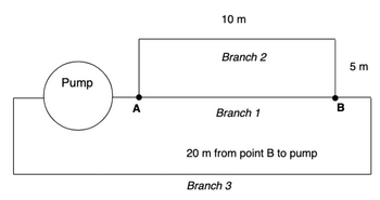
pump as a function of flow rate of water at 20 °C through the three branches of the piping system
shown below (delta P on the y axis and flow rate on the x axis; the
range of the pressure should be 0 to ~1 MPa).
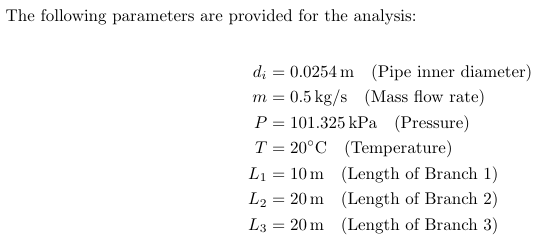
Pipe inner diameter: 0.03 m
Pipe material: copper
Typical mass flow rate of interest: 0.5 kg/s
Ignore minor losses of tee's at points A and B and any features of branch 3
Consider minor losses of two 90° elbows in branch 2

Transcribed Image Text:Pump
A
10 m
Branch 2
Branch 1
20 m from point B to pump
Branch 3
B
5 m
Expert Solution
arrow_forward
Step 1: Given data


Step by stepSolved in 7 steps with 10 images

Knowledge Booster
Learn more about
Need a deep-dive on the concept behind this application? Look no further. Learn more about this topic, mechanical-engineering and related others by exploring similar questions and additional content below.Similar questions
- 7. Pump 50mm Þ 17m Data: f = 0.0067 Pressure at 3 = 194 kN/m² gauge Velocity at 3 = 2.7 m/s p = 830 kg/m³ Pump efficiency = 88% Motor efficiency = 84% Pressure at 1 is atmospheric Velocity at 1 is negligible Determine required input power to motor [1.64 kW] 8. 200mm turbine water gen Data: At 1, p = 230 kN/m² gauge, v = At 2, p = 0 = 0 gauge, v = 0 Turbine efficiency = 80% Generator efficiency = 90% 3.6 m/s %3D Determine output power from generator [19.3 kW]arrow_forwardPlease solve accurate...arrow_forward02 h, are 12m. The pump efficiency is 79%, and the pump is driven by an electric motor. A pump moves water @10°C from a lake into a large, pressurized holding tank as shown. The flow rate, Q. is 375 L/min, and the piping system losses, 1) Sketch the setup (simple schematic is good), 2) label the z datum, and 3) identify and label the boundary conditions (P, V, and z) at 1 and 2 for use in a) the General Energy Equation (GEE). Provide values and units for the boundary conditions. Hint: For identifying good locations for boundary conditions, where are the velocities approximately zero? b) Calculate the head added to the fluid, h,, by the pump. Give your answer in units of m. Hint: Be careful with signs in manipulating the GEE. Show as many steps as you need to get your h, equation correct. Calculate the power added to the fluid by the pump in units of kW. () Determine the required electric motor size to drive the pump in units of HP. Prank = 200 kPa Holding Tank Air 6 m Pump Lakearrow_forward
- 49. Water flows at a rate of 200 GPM into a piping system connected in series. Length, diameter, and loss coefficient of each pipe are given below. For p= 62.4 Ibm/ft and u = 0.7E–3 lbm ft/s find total pressure drop and the diameter of an equivalent pipe representing this system. C) Fluid Power Theory an.. IndPitEn IlIb. Fluid Mechanics: Incompressible Viscous Flow 392 Pipe D K No. (ft) 100.00 (in) 5.00 (-) 50.00 1 2 80.00 4.50 45.00 3 70.00 4.00 65.00 4 120.00 3.50 55.00 5 90.00 3.00 15.00arrow_forwardWater at 60°F (p = 62.36 lbm/ft³ and µ = 7.536 × 10⁴ lbm/ft.s) is flowing steadily in a 2- in-diameter horizontal pipe made of stainless steel at a rate of 0.2 ft³/s (Fig. 2). Use the Colebrook equation and consult the FE Reference Handbook and appropriate table(s) for equations and properties. Write a Matlab code to determine the i. ii. iii. pressure drop, the head loss, and the required pumping power input for flow over a 200-ft-long section of the pipe. 2 in 0.2 ft³/s water -200 ft-arrow_forward1. A piston-cylinder is producing a viscous oil flow, which has the flow rate of Q, radius R=1.5 mm, and stroke L-5 mm. The fluid density is p = 800 kg/m³ and the viscosity is μ = 0.5 Pa-s. The pressure to drive the flow is p=6.25 Pa. a. How many non-dimensional groupings can be obtained? Derive them. b. If the flow transitions at Re = PV(2R) =2300. Is the generated flow laminar or turbulent given Q=20 mL/s? LL c. Assume the pressure gradient is uniform on the cross-section and can be calculated using OP=-. The velocity profile in the cylinder is u(r) = ax - [1-(²]. Sketch the velocity profile. Calculate the shear stress at the R² ap 2UÔI cylinder wall and label the direction. d. Calculate the flow rate Q with the velocity profile in (c).. e. If the shear stress is uniform over the cross-section, i.e. T = C, what's the pressure gradient distribution and sketch it? L L. Rarrow_forward
- K = 1.4*10-4arrow_forwardCan you please find solution for this question,thanksarrow_forwardDescribe the methodology for obtaining the pump curve in a project, where data are collected at five points with different pressures in the pump (10 psi, 15 psi, 20 psi, 25 psi and 30 psi), where to find these flow rates Q a 1000 ml bottle is used and the time required to fill it is timed, for each of the pump's five pressure points. The gauge pressure H in meters of water column reached must also be observed in order to construct the HxQ graph of the pump. This entire process is carried out for three different types of piping systems, each with its characteristic pressure drops.arrow_forward
- The pressure of a reactor vessel can be adjusted bychanging either the inlet or outlet gaseous flow rate. Theoutlet flow is kept fixed as long as the tank pressure remainsbetween 100 and 120 psi, and pressure changes are treatedby manipulating the inlet flow control valve. However, if thepressure goes higher than these limits, the exit gas flow isthen changed. Finally, if the pressure exceeds 200 psi, a ventvalve on the vessel is opened and transfers the gas to a storagevessel. Design a control scheme that meets the performanceobjectives. Draw a process instrumentation diagram for theresulting control systemarrow_forwardNeeds Complete solution with 100 % accuracyarrow_forward
arrow_back_ios
arrow_forward_ios
Recommended textbooks for you
 Elements Of ElectromagneticsMechanical EngineeringISBN:9780190698614Author:Sadiku, Matthew N. O.Publisher:Oxford University Press
 Mechanics of Materials (10th Edition)Mechanical EngineeringISBN:9780134319650Author:Russell C. HibbelerPublisher:PEARSON
 Thermodynamics: An Engineering ApproachMechanical EngineeringISBN:9781259822674Author:Yunus A. Cengel Dr., Michael A. BolesPublisher:McGraw-Hill Education
 Control Systems EngineeringMechanical EngineeringISBN:9781118170519Author:Norman S. NisePublisher:WILEY
 Mechanics of Materials (MindTap Course List)Mechanical EngineeringISBN:9781337093347Author:Barry J. Goodno, James M. GerePublisher:Cengage Learning
 Engineering Mechanics: StaticsMechanical EngineeringISBN:9781118807330Author:James L. Meriam, L. G. Kraige, J. N. BoltonPublisher:WILEY

Elements Of Electromagnetics
Mechanical Engineering
ISBN:9780190698614
Author:Sadiku, Matthew N. O.
Publisher:Oxford University Press

Mechanics of Materials (10th Edition)
Mechanical Engineering
ISBN:9780134319650
Author:Russell C. Hibbeler
Publisher:PEARSON

Thermodynamics: An Engineering Approach
Mechanical Engineering
ISBN:9781259822674
Author:Yunus A. Cengel Dr., Michael A. Boles
Publisher:McGraw-Hill Education

Control Systems Engineering
Mechanical Engineering
ISBN:9781118170519
Author:Norman S. Nise
Publisher:WILEY

Mechanics of Materials (MindTap Course List)
Mechanical Engineering
ISBN:9781337093347
Author:Barry J. Goodno, James M. Gere
Publisher:Cengage Learning

Engineering Mechanics: Statics
Mechanical Engineering
ISBN:9781118807330
Author:James L. Meriam, L. G. Kraige, J. N. Bolton
Publisher:WILEY