
Elements Of Electromagnetics
7th Edition
ISBN: 9780190698614
Author: Sadiku, Matthew N. O.
Publisher: Oxford University Press
expand_more
expand_more
format_list_bulleted
Related questions
Question
What is the C or T, the X and Y components and the load of each member. Also when you put the answer, could you put it like it is on the image.
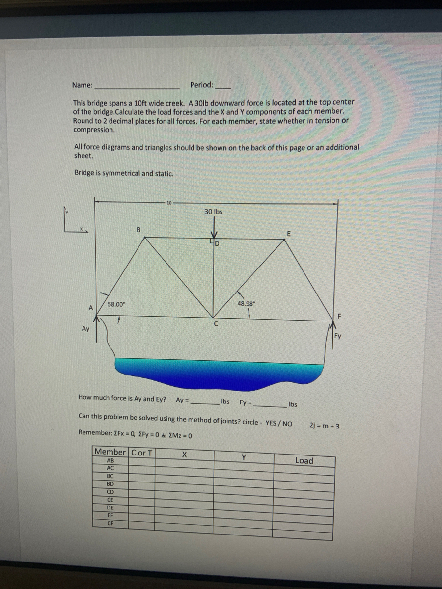

Transcribed Image Text:**Bridge Structural Analysis Exercise**
**Name:** ____________
**Period:** _____
This exercise involves analyzing a bridge structure that spans a 10ft wide creek. A 30lb downward force is exerted at the top center of the bridge. Your task is to calculate the load forces and the X and Y components for each member of the bridge. Round off your answers to two decimal places. For each member, specify whether it is in tension or compression.
All diagrams and triangle representations should be drawn on the back of this page or on an additional sheet. The bridge is assumed to be symmetrical and static.
**Diagram Explanation:**
- The bridge diagram is a symmetrical truss structure. The top central point is marked with a downward force of 30 lbs.
- The X-axis runs horizontally, and the Y-axis runs vertically.
- Notations for key points of interest are A, B, C, D, E, and F.
- Angles of 58.00° and 48.98° are labeled to help with trigonometric calculations of forces.
- Support reactions Ay and Fy are shown at the base of the structure.
**Questions:**
- Calculate the forces Ay and Ey.
- Ay = _________ lbs
- Fy = _________ lbs
- Determine if this problem can be solved using the method of joints. Circle: YES / NO
- Note the equilibrium equations:
- ∑Fx = 0
- ∑Fy = 0
- ∑MZ = 0
**Table for Analysis:**
| Member | C or T | X | Y | Load |
|--------|--------|----|----|------|
| AB | | | | |
| AC | | | | |
| BC | | | | |
| BD | | | | |
| CD | | | | |
| CE | | | | |
| DE | | | | |
| EF | | | | |
| CF | | | | |
**Instructions:**
1. Fill out the table for each member of the bridge, noting whether the member is in compression (C) or tension (T) and calculating the X and Y force components along with the total
Expert Solution
This question has been solved!
Explore an expertly crafted, step-by-step solution for a thorough understanding of key concepts.

Step by stepSolved in 4 steps

Knowledge Booster


Learn more about
Need a deep-dive on the concept behind this application? Look no further. Learn more about this topic, mechanical-engineering and related others by exploring similar questions and additional content below.Similar questions
- Looking for quick & Correct answer.arrow_forwardPlease show your step by step solution. Draw a figure and Free Body Diagram (FBD) whenever necessary. Use 4 decimal places in your solution and 2 decimal places in your final answer.arrow_forwardFill in all blanks before submission. Round the answer to the nearest integer The figure shows a rod of length 6 ft and weight 100 lb hinged to the ground at point A. The rod rests on a stone in the shape of a sphere of radius 3ft. The center of the sphere O is located at a distance of 5 ft from point A. The normal reaction N between the sphere and the rod is lb. The horizontal component of the reaction at A is lb while the vertical component of the reaction at A is lb. 6 ft The magnitude of the reaction at A is lb. The angle of the reaction at A is 3 ft 0 5 ftarrow_forward
- Need the 2nd question solved please. the first one has been donearrow_forwardPLEASE ANSWER IT COMPLETELY. SHOW COMPLETE SOLUTION. FINAL ANSWER MUST BE IN 3 DECIMAL POINTS. DO NOT ROUND OFF INTERMEDIATE NUMBER.arrow_forwardPlease solve it in a handwritten format with a free body diagram. Don't use chat gpt. (Diagram is mandatory) Mechanical engineering -arrow_forward
- Hello, please answer as soon as possible. Choose from the given choices/options below the question. Show complete solution if necessary. Thank you for your help. I’ll rate you with like/upvote.arrow_forwardSimple Machines-Levers, Inclined Planes, and Pulleys Directions: Use the appropriate equation to answer the following questions. All answers should be recorded below or in your Engineering Design journal. Remember to show all work. A lever has an effort arm that is 5 meters long and a resistance (load) arm that is 3.5 meters long. How much effort is needed to lift a 100 Newton weight? 5K i). Draw the figure representing the problem ii). How much effort is needed to lift a 100 Newton weight? iii). What is the Actual Mechanical Advantage 1. 5m i) AOON 5-5marrow_forwardQ1. As shown in the image below, the force acting on the box is F = (C · s²) Determine the work done by force F to the box when the box has displaced s = 1.7 m. Please pay attention: the numbers may change since they are randomized. Negative sign must be included if the work done is negative. Your answer must include 2 places after the decimal point, and proper Sl unit. N, where constant C = 6 and s is displacement in m. S F -arrow_forward
- The 80-lb door has its center of gravity at G. (Figure 1) Figure 1 of 1 18 in. 24 in. 24 in. 18 in.arrow_forward2. For this series of 4 questions, a man sits in the chair which is pin-connected to the 10-m frame BC. Frame BC rotates counterclockwise. Your final goal is to determine the magnitude of the support force N exerted by the chair on the man at the instant = 30°. But before that, you need to answer some other questions. Please pay attention: the numbers may change from problem to problem since they are randomized. 4) If at this instance he has a speed of 5.2 m/s, which is increasing at 0.8 m/s², and the man has a mass of 90 kg, determine the magnitude of the support force N exerted by the chair on the man at the instant = 30°. Your answer must include 2 places after the decimal point, and the proper unit. Take g = 9.81 m/s². C Your Answer: Answer 10 m 0 units Barrow_forwardCan anyone help me with this questionarrow_forward
arrow_back_ios
SEE MORE QUESTIONS
arrow_forward_ios
Recommended textbooks for you
- Elements Of ElectromagneticsMechanical EngineeringISBN:9780190698614Author:Sadiku, Matthew N. O.Publisher:Oxford University Press
 Mechanics of Materials (10th Edition)Mechanical EngineeringISBN:9780134319650Author:Russell C. HibbelerPublisher:PEARSON
 Thermodynamics: An Engineering ApproachMechanical EngineeringISBN:9781259822674Author:Yunus A. Cengel Dr., Michael A. BolesPublisher:McGraw-Hill Education
  Control Systems EngineeringMechanical EngineeringISBN:9781118170519Author:Norman S. NisePublisher:WILEY
 Mechanics of Materials (MindTap Course List)Mechanical EngineeringISBN:9781337093347Author:Barry J. Goodno, James M. GerePublisher:Cengage Learning
 Engineering Mechanics: StaticsMechanical EngineeringISBN:9781118807330Author:James L. Meriam, L. G. Kraige, J. N. BoltonPublisher:WILEY
Elements Of Electromagnetics
Mechanical Engineering
ISBN:9780190698614
Author:Sadiku, Matthew N. O.
Publisher:Oxford University Press
Mechanics of Materials (10th Edition)
Mechanical Engineering
ISBN:9780134319650
Author:Russell C. Hibbeler
Publisher:PEARSON
Thermodynamics: An Engineering Approach
Mechanical Engineering
ISBN:9781259822674
Author:Yunus A. Cengel Dr., Michael A. Boles
Publisher:McGraw-Hill Education
Control Systems Engineering
Mechanical Engineering
ISBN:9781118170519
Author:Norman S. Nise
Publisher:WILEY
Mechanics of Materials (MindTap Course List)
Mechanical Engineering
ISBN:9781337093347
Author:Barry J. Goodno, James M. Gere
Publisher:Cengage Learning
Engineering Mechanics: Statics
Mechanical Engineering
ISBN:9781118807330
Author:James L. Meriam, L. G. Kraige, J. N. Bolton
Publisher:WILEY