Elements Of Electromagnetics
7th Edition
ISBN: 9780190698614
Author: Sadiku, Matthew N. O.
Publisher: Oxford University Press
expand_more
expand_more
format_list_bulleted
Question
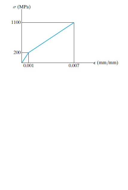
The stress–strain diagram for a material can be approximated by the two line segments shown. If a bar having a diameter of 80 mm and a length of 1.5 m is made from this material, determine the critical load provided the ends are fixed. Assume that the load acts through the axis of the bar. Use Engesser’s equation.

Transcribed Image Text:(MPa)
1100
200
(mm/mm)
0.001
0.007
Expert Solution
This question has been solved!
Explore an expertly crafted, step-by-step solution for a thorough understanding of key concepts.
Step by stepSolved in 2 steps with 4 images

Knowledge Booster
Learn more about
Need a deep-dive on the concept behind this application? Look no further. Learn more about this topic, mechanical-engineering and related others by exploring similar questions and additional content below.Similar questions
- In a standard tensile test a steel rod of 7/8 in. in diameter is subjected to a tension force of 17 kips. Determine the ratio of the shear modulus to the modulus of elasticity of a material whose Poisson's ratio is 0.25.arrow_forwardParvinbhaiarrow_forwardAn axial load of 100 kN is applied to a flat bar 20 mm thick, tapering in width from 120 mm to 40 mm in a length 0f 10 m. Assuming E=200 GPa, determine the total elongation of the bar.arrow_forward
- A plastic rod is 200mm long and 15mm in diameter. If a tensile load of 300N is applied to it, determine the change in its length and the change in its diameter. Assume Modulus of elasticity (E) = 2.70 GPa, and poisson's ratio (v) = 0.4. indicate free body diagramarrow_forwardA hallow cylindrical steel column with an outer diameter of 200 mm and an inner diameter of 180 mm is subjected to a compressive load of 200 kN. The yield strength of the steel is 250 MPa. Calculate the factor of safety for the column using the maximum normal stress theory.arrow_forwardThe part shown is loaded at point C with 290 N in the positive x direction and at point E with 200 N in the positive y direction. The diameter of the bar ABD is 12 mm. Evaluate the likelihood of failure in section AB. 55 dia, d B Q ********* where P= 290 N, Q = 200 N, and d = 12 mm NOTE: This is a multi-part question. Once an answer is submitted, you will be unable to return to this part.arrow_forward
- Question 1 A tensile load of 40 kN is acting on a rod of diameter 40 mm and of length 4 m. A bore of diameter 20 mm is made centrally on the rod. To what length the rod should be bored so that the total extension will increase 30% under the same tensile load. Take E = 2 x 10° N/mm².arrow_forwardjust final answer A rigid component ABC is supported by a pin-connected member (1). The member has a rectangular cross-section with dimensions of 54 mm and 48 mm. The elasticity modulus of the material is 169 GPa. If L1=2421 mm, L2=1226 mm, L3=2272 mm, and L4=2072 mm; Determine the maximum normal stress (MPa) in member (1) without buckling.arrow_forwardpts) The rigid L-shaped bar show below is supported by pin at A, steel rod at L, and titanium rod at C. Determine the force in the rods when the 2 k/ft distributed load is applied on arm CA. Determine the reaction at support A. Also, determine the strains in the steel and titanium rods. Show the free body diagrams. Show all calculations. See attached Material Properties Table for required parameters in your calculation. Rod: Steel A-36 Diameter = 3/4" L = 5 ft Rigid 2 kip/ft C 8 ft Rigid Rod: Titanium Alloy Diameter = 3/4" L = 4 ft L 5 ft Aarrow_forward
- If load P = 22.9 kips, determine the normal force in bar (1). D P A 6 ft 51.9 kips 44.8 kips 27.3 kips 38.2 kips O 40.4 kips B (1) 4 ftarrow_forwardA steel rod with length equal to 12 ft, has a diameter of 0.8 inches in quarter of its length and a diameter of 0.4 inches the rest. If it is subjected to a tensile load of 6,500 lbs, what will be the total deformation of the bar if it has a modulus of elasticity E = 29.5 10^6 psi.arrow_forwardRods AB and BC each have a diameter of 5 mm. If the load of P = 1.5 kN is applied to the ring, determine the average normal stress in each rod if 0 = 50°. B Figure Q1arrow_forward
arrow_back_ios
SEE MORE QUESTIONS
arrow_forward_ios
Recommended textbooks for you
 Elements Of ElectromagneticsMechanical EngineeringISBN:9780190698614Author:Sadiku, Matthew N. O.Publisher:Oxford University Press
 Mechanics of Materials (10th Edition)Mechanical EngineeringISBN:9780134319650Author:Russell C. HibbelerPublisher:PEARSON
 Thermodynamics: An Engineering ApproachMechanical EngineeringISBN:9781259822674Author:Yunus A. Cengel Dr., Michael A. BolesPublisher:McGraw-Hill Education
 Control Systems EngineeringMechanical EngineeringISBN:9781118170519Author:Norman S. NisePublisher:WILEY
 Mechanics of Materials (MindTap Course List)Mechanical EngineeringISBN:9781337093347Author:Barry J. Goodno, James M. GerePublisher:Cengage Learning
 Engineering Mechanics: StaticsMechanical EngineeringISBN:9781118807330Author:James L. Meriam, L. G. Kraige, J. N. BoltonPublisher:WILEY

Elements Of Electromagnetics
Mechanical Engineering
ISBN:9780190698614
Author:Sadiku, Matthew N. O.
Publisher:Oxford University Press

Mechanics of Materials (10th Edition)
Mechanical Engineering
ISBN:9780134319650
Author:Russell C. Hibbeler
Publisher:PEARSON

Thermodynamics: An Engineering Approach
Mechanical Engineering
ISBN:9781259822674
Author:Yunus A. Cengel Dr., Michael A. Boles
Publisher:McGraw-Hill Education

Control Systems Engineering
Mechanical Engineering
ISBN:9781118170519
Author:Norman S. Nise
Publisher:WILEY

Mechanics of Materials (MindTap Course List)
Mechanical Engineering
ISBN:9781337093347
Author:Barry J. Goodno, James M. Gere
Publisher:Cengage Learning

Engineering Mechanics: Statics
Mechanical Engineering
ISBN:9781118807330
Author:James L. Meriam, L. G. Kraige, J. N. Bolton
Publisher:WILEY